Page 54
XC21
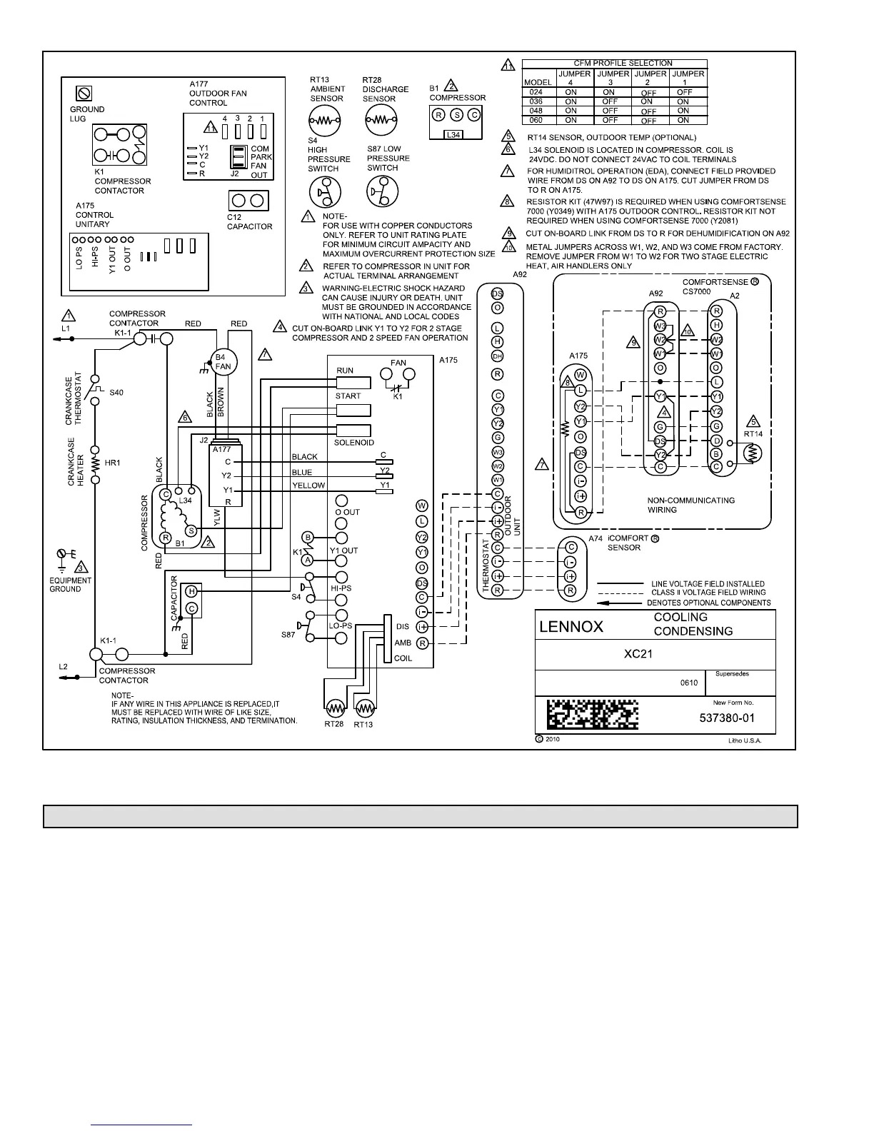
Figure 30. Typical XC21 Wiring (with icomfortt enabled, New Fan Motor with built−in surge protection and
External Surge Protection Device Removed (XC21−XXX−230−06 build)
Unit Sequence of Operations
The following figures illustrated the overall unit sequence of operations along with various pressure switches and
temperature sensor operations. The figures also illustration the use of the compressor anti−short cycle function in relations
to unit Status, Fault and Lockout LED Codes system operations interaction.

 Loading...