Page 55
XC21
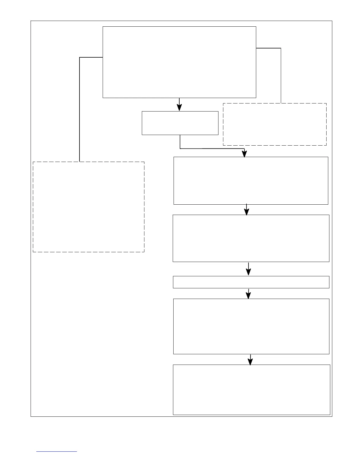
On 24VAC power−up or air conditioner control (A175)
reset, the air conditioner control shall perform the
following tasks:
1. Start the anti−short cycle delay.
2. Check temperature sensor and pressure switches at
the start of cooling demand.
3. Air Conditioner control responds to the thermostat
input after the anti−short cycle timer expires. If there is
no thermostat input, control goes to standby mode.
The air conditioner control (A175) will apply:
1. 24VAC to compressor contactor output Y1 OUT..
2. Output between 24 and 32 VDC on air conditioner
control’s ECM fan terminals ECM Y1 FAN and ECM C.
NOTE − If low pressure switch is closed, system will ignore
for 90 seconds.
The outdoor fan control (A177) will:
Receive the DC voltage signal from the outdoor control
(A175) and converted the signal to a pulse width
modulation (PWM) signal. Jumper settings will determine
fan PWM OUT fan speed.
NOTE Refer to table 15 for jumper settings.
For low pressure (S87) and high (S4)
switches sequence of operations, see
figures 32 and 33.
For temperature switch RT28
sequence of operations, see figure 34.
Room thermostat calls for high (two−stage) cooling.
The air conditioner control will apply::
1. 24VAC to second−stage solenoid output (E34) that will
energized after the first−stage compressor has been
active for a minimum of five (5) seconds.
2. Output between 24 and 32 VDC on air conditioner
control’s second−stage ECM fan terminals ECM Y2
AND ECM C.
The outdoor fan control (A177) will:
Receive the DC voltage signal from the outdoor control
(A175) and converted the signal to a pulse width
modulation (PWM) signal. Jumper settings will determine
fan PWM OUT fan speed.
NOTE Refer to table 15 for jumper settings.
Two−stage Ambient Lock−in
Temperature
Should the ambient temperature be below
the selected two−stage lock−in
temperature (jumper in place on E48
jumper pin strip) , the two−stage solenoid
output will be energized after the
one−stage minimum run timer expires
Energize two−stage ECM fan outputs
ECM Y2 Fan and Y2 input/output.
Appropriate system status LED code is
displayed to indicate two−stage heat
lock−in.
Room thermostat calls for
low (one−stage) cooling.
Figure 31. One−Stage and Two−Stage Cooling Sequence of Operation

 Loading...