Page 33
XC21
COIL TEMPERATURE SENSOR
This model does not use a coil temperature sensor. The
cable assembly attached to the main control’s E30
connection has a 10K resister installed between pins 5 and
6 as illustrated in figure 19.
10K resistor
High Discharge Line
Temperature Sensor
Ambient Air
Temperature
Sensor
Figure 19. 10k Resistor Location
TESTING AMBIENT (RT13) AND HIGH DISCHARGE
LINE TEMPERATURE (RT28) SENSORS
Sensors connect through a field-replaceable harness
assembly that plugs directly into the main control. Through
these sensors, the main control can monitor outdoor
ambient and discharge line temperature fault conditions.
As the detected temperature changes, the resistance
across the sensor changes. Tables 7 and 8 lists how the
resistance varies as the temperature changes for both type
of sensors. Sensor resistance values can be checked by
ohming across pins shown in table 6.
When a sensor indicates a resistance value that is not
within the range as listed in table 6, then the following
condition may be present:
S Sensor detects an out−of−range outdoor ambient air
temperature condition and will display LED alert code
on the main control.
S The sensor is operating normally when the ambient air
temperature at the sensor is below or above the main
control’s expected ohm values. The main control will
indicate the sensor as faulty, however under this
scenario, the sensor is not actually faulty.
S Once the outdoor ambient air temperature has
returned to within the sensor’s normal operating range,
the LED alert code will automatically stop.
Table 6. Sensor Temperature / Resistance Range
Sensor Temperature Range °F (°C) Resistance values range (ohms)
Pins/ Wire
Color
Outdoor
(Ambient)
−40ºF to 140ºF (−40ºC to 60ºC) 280,000 to 3750 3 and 4 (Black)
Discharge −35ºF to 310ºF (−37ºC to 154ºC) 41,000 to 103 1 and 2 (Yellow)
Note: Sensor resistance decreases as sensed temperature increases (see tables 7 and 8.
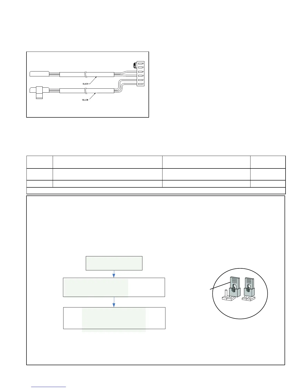
E33 JUMPER (TEST) PINS
PLACING THE JUMPER ON THE E33 JUMPER PINS (SEE PAGE 26 FOR LOCATION OF E33 JUMPER PINS) ALLOWS THE TECHNICIAN TO
S CLEAR COMPRESSOR ANTI−SHORT CYCLE DELAY.
S CLEAR FIVE−STRIKE FAULT LOCKOUTS HIGH / LOW PRESSURE SWITCHES AND HIGH DISCHARGE TEMPERATURE SENSOR.
S SET THE UNIT CAPACITY CODE (PROCEDURE PROVIDED ON PAGE 41).
NOTES:
1 PLACING A JUMPER ON THE E33 PINS WILL NOT RESET (REBOOT) THE MAIN CONTROL (A175). THE ONLY WAY TO RESET THE OUTDOOR UNIT IS TO
CYCLE THE 24VAC POWER TO THE OUTDOOR UNIT’S MAIN CONTROL.
2 IF THE JUMPER REMAINS ON THE E33 PINS FOR LONGER THAN FIVE SECONDS, THE MAIN CONTROL WILL IGNORE THE JUMPER ON E33 PINS AND
REVERT TO NORMAL OPERATION.
Y1 Active
PLACE A JUMPER ON
1
THE E33 PINS FOR LONGER THAN
ONE SECOND
2
. THEN REMOVE JUMPER AND PLACE IN
JUMPER OFF POSITION.
CLEARS ANY SHORT CYCLE LOCKOUT AND FIVE STRIKE
FAULT LOCKOUT FUNCTION, IF APPLICABLE. NO OTHER
FUNCTIONS WILL BE EXECUTED AND UNIT WILL CONTINUE
IN THE MODE IT WAS OPERATING.
JUMPER
OFF
JUMPER
ON
FACTORY DEFAULT
JUMPER SETTING
Figure 20. Multi−Function E33 Jumper (Test) Pin

 Loading...