XP17 - 2 to 5 Ton Heat Pump / Page 4
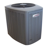
COMPRESSOR
Scroll Compressor
Compressor features high
efciency with uniform suction
ow, constant discharge ow, high
volumetric efciency and quiet
operation.
Compressor consists of two
involute spiral scrolls matched
together to generate a series
of crescent shaped gas
pockets between them. During
compression, one scroll remains
stationary while the other scroll
orbits around it. Gas is drawn
into the outer pocket, the pocket is sealed as the scroll
rotates. As the spiral movement continues, gas pockets
are pushed to the center of the scrolls. Volume between
the pockets is simultaneously reduced.
When the pocket reaches the center, gas is now at high
pressure and is forced out of a port located in the center
of the xed scrolls.
During compression, several pockets are compressed
simultaneously resulting in a smooth continuous
compression cycle.
Continuous ank contact, maintained by centrifugal
force, minimizes gas leakage and maximizes efciency.
Scroll compressor is tolerant to the effects of slugging
and contaminants. If this occurs, scrolls separate,
allowing liquid or contaminants to be worked toward the
center and discharged.
Low gas pulses during compression reduces
operational sound levels.
Compressor motor is internally protected from
excessive current and temperature.
Compressor is installed in the unit on resilient rubber
mounts for vibration free operation.
Factory installed crankcase heater.
Crankcase Heater
Crankcase heater prevents migration of liquid
refrigerant into compressor and ensures proper
compressor lubrication.
Compressor Sound Dampening System
A polyethylene compressor cover containing a 2 inch
thick batt of berglass insulation for better sound
dampening.
All open edges are sealed with a one-inch wide hook
and loop fastening tape.
I
J
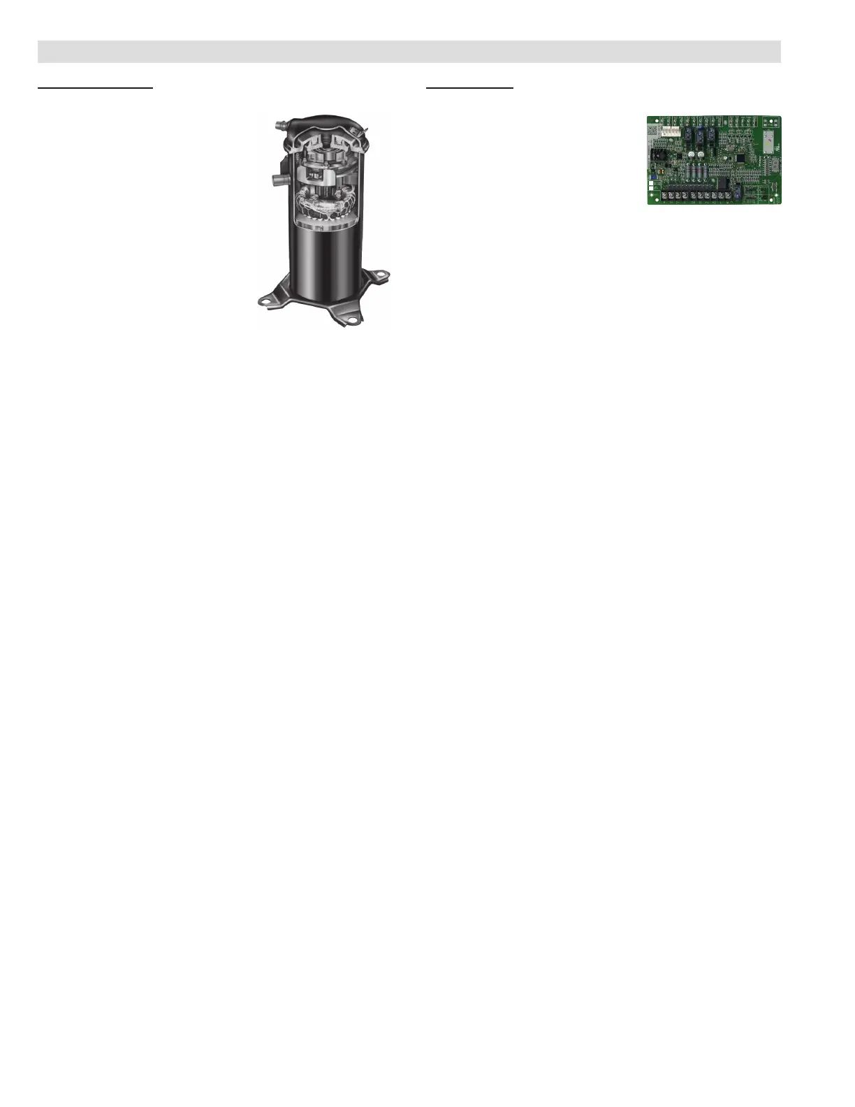
CONTROLS
icomfort
®
Control
Advanced icomfort
®
control
communicates information about
various operating parameters
in the heat pump outdoor unit
to the optional icomfort Wi-
Fi™ Thermostat to constantly
maintain the highest level of comfort, performance and
efciency available.
Connections for connecting a conventional heat pump
thermostat are also provided.
Auto Conguration - On start-up the control
automatically sends a description of the unit to the
optional icomfort™ Thermostat to automatically
congure the number of stages and features available.
Seven-Segment Display
Seven-segment display shows information about
outdoor unit type and capacity and also displays alerts
for common fault conditions (electrical and mechanical).
Control also features:
• Compressor anti-short cycle delay (5 minutes).
• Compressor defrost shift delay - Adjustable 0 (factory)
or 30 seconds.
• Demand defrost using outdoor ambient air
temperature, coil temperature and compressor run-
time inputs. 14 minute maximum defrost time.
• Selectable defrost termination temperature - 50, 70,
90 or 100ºF. Default setting is 50°F.
• High and low pressure switch monitoring with
provisions for lockout.
• Five-Strike lockout protection protects compressor.
• Outdoor air temperature and sensor monitoring.
• Fan cycling operates outdoor fan for 5 minutes when
outdoor ambient air temperature is between 15°F and
35°F and the compressor has been off for 25 to 30
minutes. Reduces the potential for ice buildup on the
fan orice ring. User selectable 5 minutes on or off
(default setting).
• Lennox Humiditrol
®
Whole Home Dehumidication
System (EDA) compatible.
• EEPROM storage of all local congurations.
K
FEATURES
 Loading...