17
l
4.2.2 CE-typical drive system
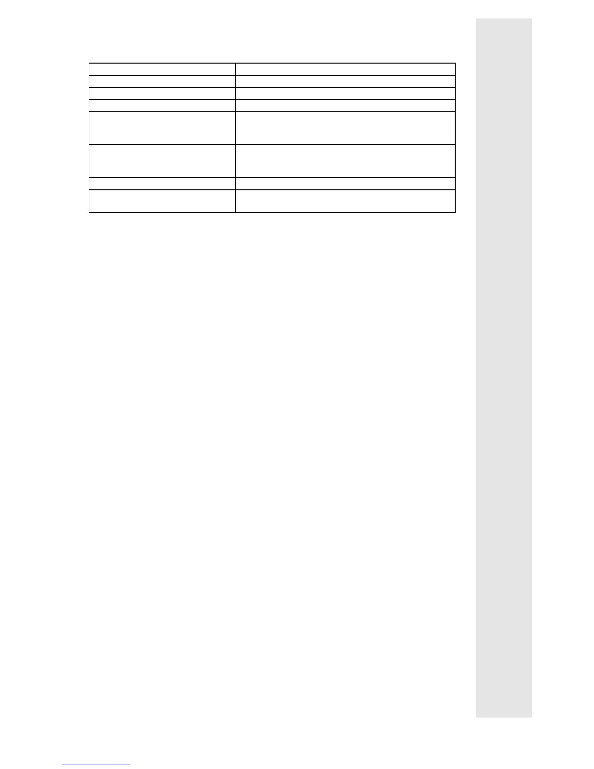
Components of a CE-typical drive system
System components Specification
Controller Controller of the types 531 to 534
RFI filter Data and allocation see chapter 3 "Accessories"
Mains choke Data and allocation see chapter 3 "Accessories"
Armature and field cable Screened power cable with tinned E-CU braid with
85 % optical coverage.
Tested maximum length: 50 m
Mains cable between RFI filter and
mains choke and between mains
choke and controller
As from cable length of 200 mm:
screened power cable with tinned E-CU braid with
85 % optical coverage.
Control cables Screened signal cable type LIYCY
Motor DC motor with separate excitation
Lenze series GFQ, GFR or similar
Note:
Controller, RFI filter, and mains choke are located on one mounting plate.
Installation of the CE typical drive system
The electromagnetic compatibility of a drive system depends on the type and
accuracy of the installation.
Take special care with
− filters
− screening
− grounding
Filters
• Only use the RFI filters and mains chokes allocated to the controllers (see
chapter 3 "Accessories").
− RFI filters reduce non-permissible high-frequency interferences to a
permissible value.
− Mains chokes reduce low-frequency interference which depends primarily
on the motor cables and their length.
For motor cables which are longer than 50 m additional measures are
required.
Screening
• Screen all cables from and to the controller.
• Make sure that motor cables are separated from signal and mains cables
when laying the cables.
• Avoid a common terminal board for mains input and motor output.
• The cables must be laid as close as possible to the reference potential.
Dangling cables are like antennas.

 Loading...


