EasyManua.ls Logo

Lenze 8200 series User Manual

Lenze 8200 series
74 pages
To Next Page IconTo Next Page
To Previous Page IconTo Previous Page
Page #38 background imageLoading...
Page #38 background image
Commissioning
UOMu_^MVMO 5-5
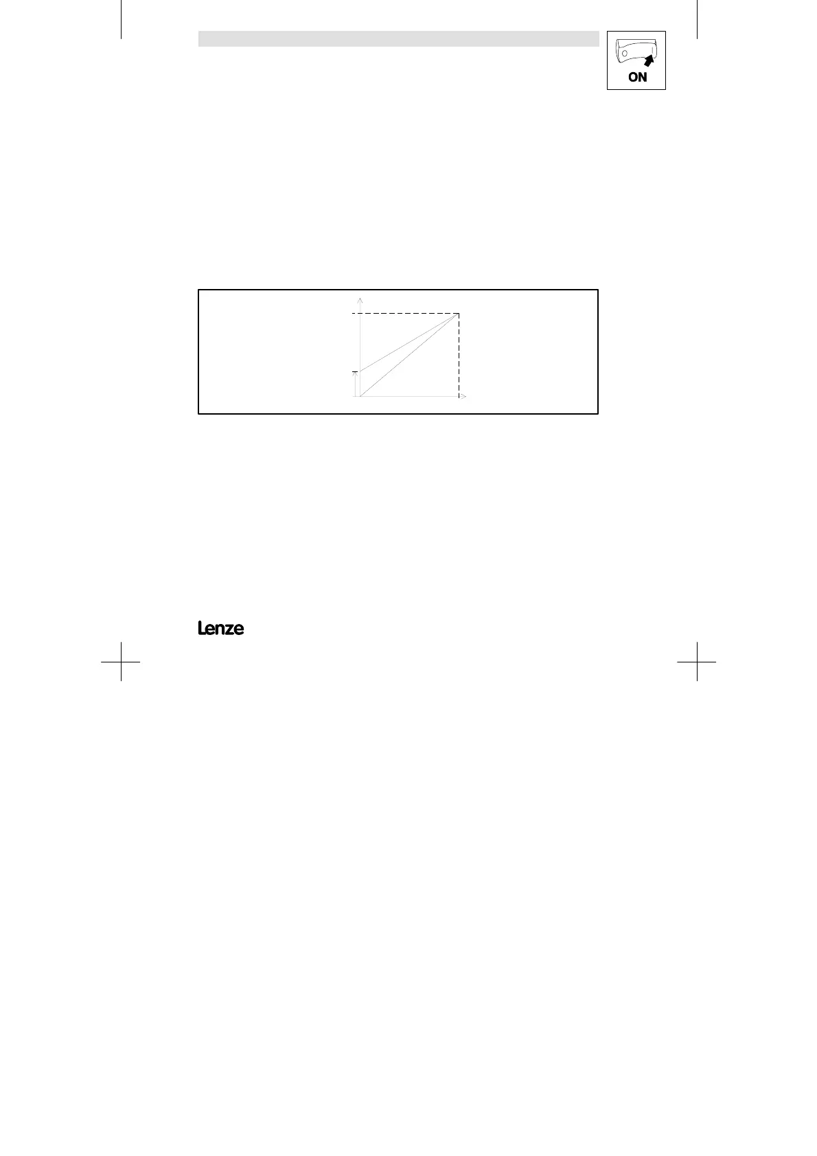
Important D With the setting of f
dmin
>f
dmax
the field frequency is limited to f
dmax
.
D When selecting the setpoint by means of JOG values, f
dmax
acts as limitation.
D f
dmax
is an internal standardization variable:
- Use the LECOM interface only for important modifications, when the controller is
inhibited.
D Observe the maximum motor speed!
D f
dmin
is only effective under the following conditions:
- With analog setpoint selection.
- With the motor potentiometer function ”DOWN”.
Special features
D With field frequencies f
d
> 240Hz:
- The overcurrent switch-off can be activated.
fd
C011
(fdmax)
C010
(fdmin)
0 % 100 %
hPRKMMSO
Artisan Technology Group - Quality Instrumentation ... Guaranteed | (888) 88-SOURCE | www.artisantg.com

Table of Contents

Questions and Answers:

Lenze 8200 series Specifications

General IconGeneral
CategoryInverter
Output voltage range0 V to input voltage
Control modesvector control
Communication interfacesRS485, CANopen, Profibus, Ethernet
Protection featuresOvercurrent, overvoltage, undervoltage, short circuit, overtemperature
Relative humidity95 % (non-condensing)
Protection classIP20

Summary

Preface and general information

About these Operating Instructions

Explains the purpose and usage of the operating instructions.

Scope of delivery

Lists the items included in the delivery.

Legal regulations

Details applicable legal and EC directives for the controllers.

Safety information

General safety information

Provides essential safety and application notes for controllers.

Layout of the safety information

Explains the structure and meaning of safety icons and signal words.

Residual hazards

Lists remaining hazards and precautions for operator safety.

Technical data

General data/application conditions

Details vibration resistance, humidity, temperature, and installation height.

Rated data (Operation with 150 % overload)

Lists electrical and performance data for various types under overload.

Fuses and cable cross-sections

Specifies fuse types and cable cross-sections for single drives.

Dimensions

Details controller dimensions based on mechanical installation.

Installation

Mechanical installation

Key considerations for controller installation and environment.

Electrical installation

Crucial notes for electrical installation and mains types.

Installation of a CE-typical drive system

User responsibility for EC directives and EMC compliance.

Commissioning

Before you switch on

Checks required before the initial switch-on of the controller.

Short set-up (Factory setting)

Step-by-step procedure for initial switch-on and basic operation.

Adapt machine data

How to select the minimum and maximum field frequencies.

Optimisation of the operating characteristic of the drive

Choosing between V/f control modes with or without boost.

During operation

Configuration

Basics

Explains the purpose and methods of controller configuration.

Code table

How to read and interpret the parameter code table.

Troubleshooting and fault elimination

Troubleshooting

Covers general troubleshooting steps and displays.

Fault analysis using the history buffer

Explains how to use the history buffer for fault tracing.

Fault indications

Details fault displays, causes, and remedies.

Reset of fault indications

Procedures for resetting fault indications and TRIP status.

Accessories (Overview)

Accessories for all types

Lists available accessories applicable to all controller types.

Software

Lists software and order numbers for controller management.

Type-specific accessories

Details accessories specific to different controller types.

Index

Related product manuals