Wirin g accord ing to EM C
Always observe these basic rules
9
l
EDBEMV82EV EN 3.0
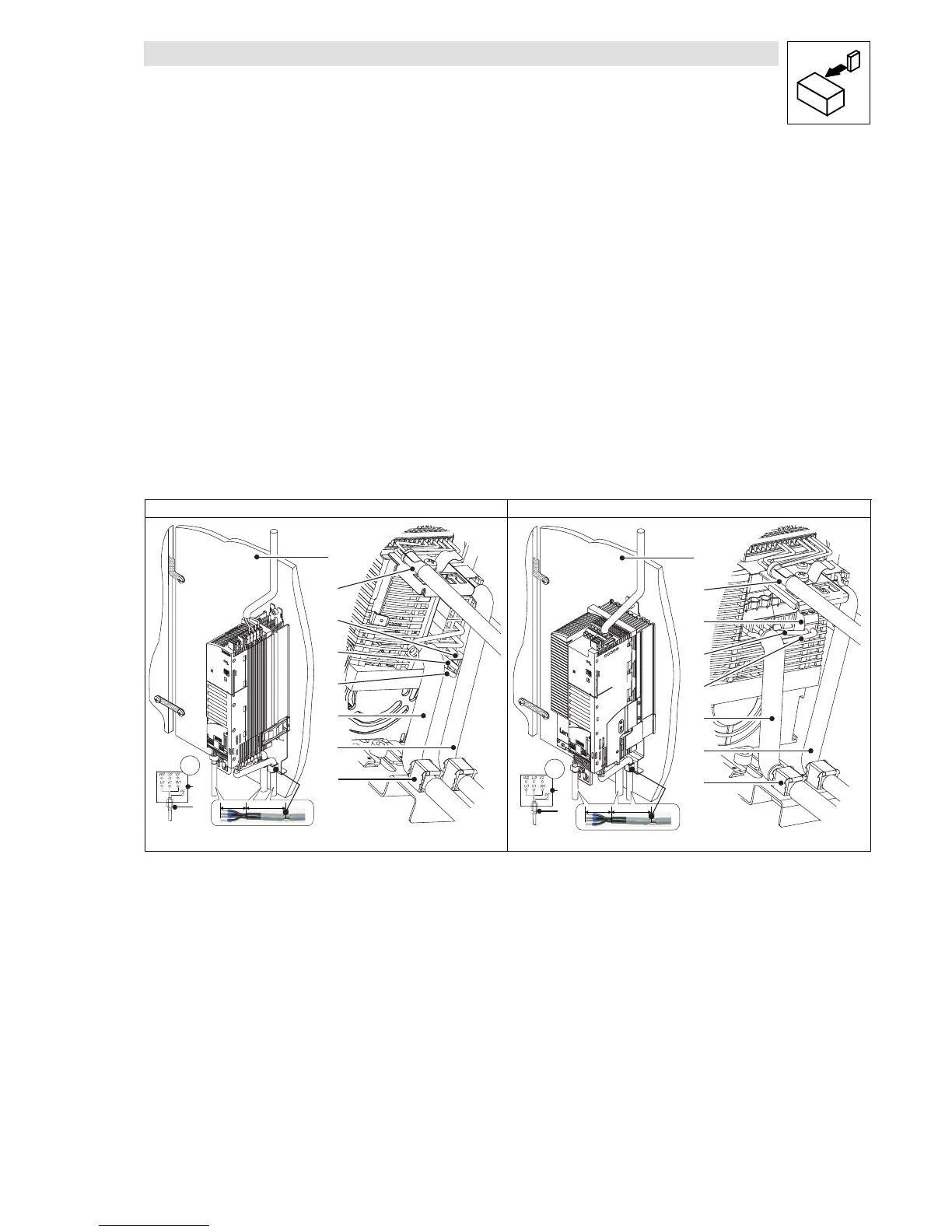
3 Wiring according to EMC (structure of a CE-typical drive
system)
3.1 Basic rules
The structure of a CE-typical drive system will be more efficient by means of wiring according to
EMC. Wiring according to EMC is determined by the type of installation and the care taken.
Figure 2 shows two important rules for installation:
z
careful structure
z
good shielding
z
good earthing
z
separated cable routing
8200 v ector 0.25 ... 2.2 k W 8200 v ector 3 ... 11 kW
8200vec008
M
3~
PES
L < 500 mm
L<40mm
PE
PE
PE
8
9
PES
PES
1
2
3
4
5
6
7
0
8200vec066
M
3~
L < 500 mm
L<40mm
1
2
3
4
5
6
7
8
9
0
PES
PES
PE
PE
PE
PES
Fig. 2 Installation principle according to EMC
Mounting plate with electrically conductive surface
Control cable to function module, connect the shielding to the EMC shield sheet (PES) with a surface as large as
possible
2-pole terminal for motor PE and motor shield
PE of the motor cable
Shield of the motor cable
Shielded low-capacitance motor cable
(Core/core 1.5 mm
2
≤ 75 pF/m; from 2.5 mm
2
≤ 100 pF/m; core/shield ≤ 150 pF/m)
Shielded PTC cable or thermal contact cable
Connect the cable shields to the EMC shield sheet (PES) with a large surface. Use the enclosed shield clamps.
Star or delta connection as indicated on the motor nameplate
!
EMC cable gland (not included in the scope of supply)
 Loading...


