Wiring accord ing to EMC
Accessories
24
l
EDBEMV82EV EN 3.0
3.6.2 Brake resistor
Brake resistors can be connected to the terminals BR1 / BR2. This enables an undisturbed braking
operation (operation in generator mode)
3.6.2.1 Basic rules for wiring
z
Only use shielded cables for the brake resistor.
z
Connect the shield to the EMC shield sheet of the controller.
z
Connect the shield near the brake resistor to the mounting plate with a large contact surface
using a shield clamp.
z
Connect the shield of the control cables for digital signals (temperature monitoring T1 / T2) on
both sides - controller and brake resistor.
z
Continue the shield after the shield clamp to the terminals. Do not exceed an unshielded
cablelengthof40mm.
z
The maximum cable length amounts to 8 m.
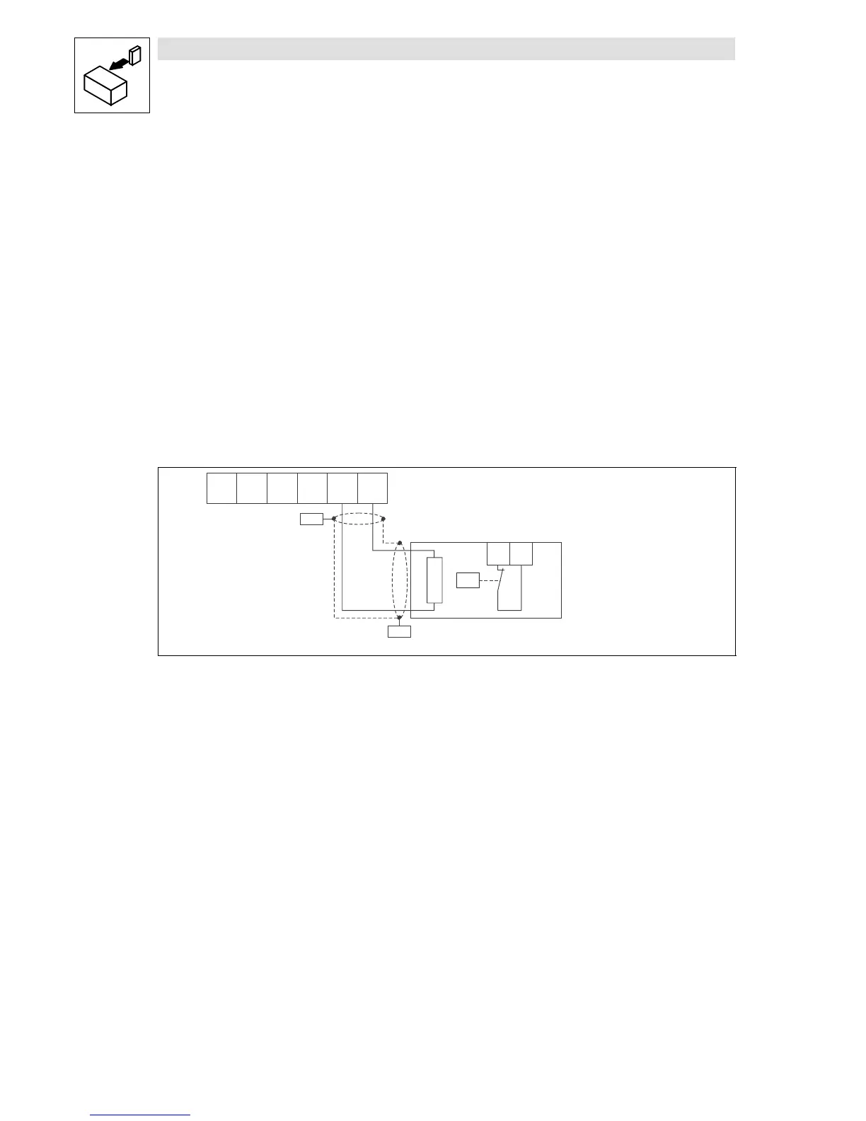
3.6.2.2 Wiring
PE
T1
T2
WV
U
BR2 BR1
X2.1
R
B
ϑ >
PES
PES
L ≤ 8m
Fig. 10 Wiring of brake resistor
PES HF-shield end by PE connection t hrough shield clamp.
 Loading...


