Electrical installation
Wiring and Configuration
MC−PBM, MC−PBS
4
l
33
BA_MC−Card EN 1.0
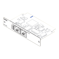
4.3.4 MC−PBM, MC−PBS
Wiring
Pin assignment Description Connection type Cable type
1
2
3
4
5
6
7
8
9
PROFIBUS connection
Pin 1: not assigned
Pin 2: not assigned
Pin 3: RxD/TxD−P(B)
Pin 4: RTS
Pin 5: M5V
Pin 6: P5V
Pin 7: not assigned
Pin 8: RxD/TxD−N(A)
Pin 9: not assigned
9−pole Sub−D socket See following table
epm−t223
RxD/TxD-P(B)
Schirm
Master
Slave
3
8
3
8
Schirm
P5V
P5V
M5VM5V
330W 330W
330W 330W
220W 220W
Schirm
3
8
RxD/TxD-N(A)
5
6
RxD/TxD-P(B)
RxD/TxD-N(A)
Slave
RxD/TxD-P(B)
RxD/TxD-N(A)
5
3
8
6
SLIO090
) Note!
The PROFIBUS cable must be terminated with its surge impedance.
Specification of the transmission cable
) Note!
Only use cables complying with the listed specifications of the PROFIBUS user
organisation.
Field Values
Specific resistance 135 ... 165 W/km, (f = 3 ... 20 MHz)
Capacitance per unit length £ 30 nF/km
Loop resistance < 110 W/km
Core diameter > 0.64 mm
Core cross−section > 0.34 mm
2
Cores Twisted double, insulated and shielded
 Loading...