Electrical installation
Wiring and Configuration
MC−CAN2
4
l
24
BA_MC−Card EN 1.0
4.3 Wiring and Configuration
4.3.1 MC−CAN2
Wiring
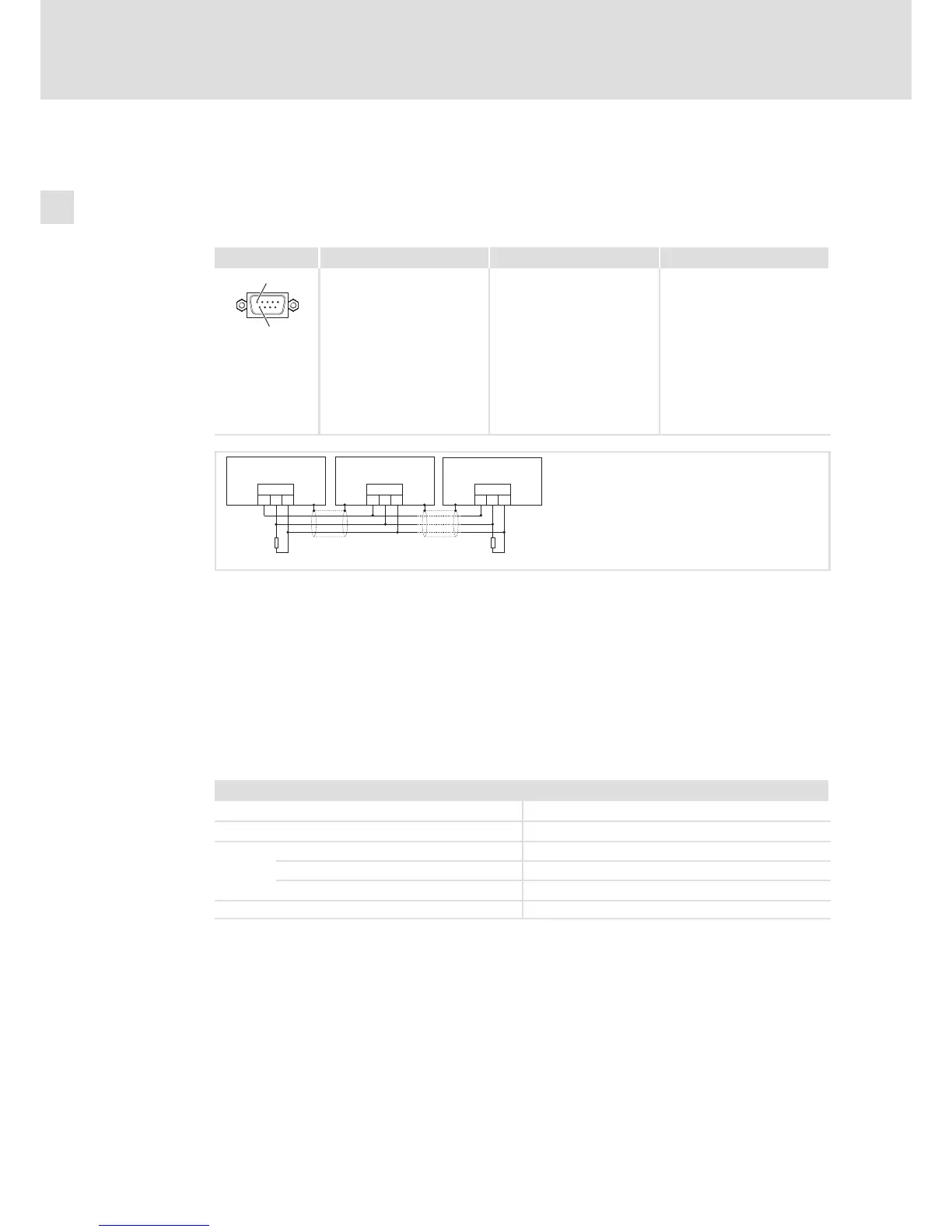
Pin assignment Description Connection type Cable type
1
6
CAN bus connection
Pin 1: not assigned
Pin 2: CAN−LOW (LO)
Pin 3: CAN−GND (CG)
Pin 4: not assigned
Pin 5: not assigned
Pin 6: CAN−GND (CG)
Pin 7: CAN−HIGH (HI)
Pin 8: not assigned
Pin 9: not assigned
9−pole SUB−D plug See following table
MC−CAN−003
CG
CAN
LO HI CG
CAN
LO HI CG
CAN
LO HI
RR
A
n
A
2
A
1
EL100−009
A1 Node 1
A2 Node 2
An Node n
CG CAN−GND
LO CAN−LOW
HI CAN−HIGH
R 120 W−bus terminating resistor
Specification of the transmission cable
We recommend the use of CAN cables in accordance with ISO 11898−2:
CAN cable in accordance with ISO 11898−2
Cable type Paired with shielding
Impedance 120 W (95 ... 140 W)
Cable resistance/cross−section
Cable length £ 300 m £ 70 mW/m / 0.25 0.34 mm
2
(AWG22)
Cable length 301 1000 m £ 40 mW/m / 0.5 mm
2
(AWG20)
Signal propagation delay £ 5 ns/m
 Loading...