Electrical installation
Wiring and Configuration
MC−ISI
4
l
30
BA_MC−Card EN 1.0
4.3.3 MC−ISI
Configuration
DIP switch for setting the mode:
DIP switch Description
1234
ON
Pos. 1 = ON: RS485 mode
Pos. 2 = ON: RS422 mode
Pos. 3 = ON/OFF: four−wire conductor/two−wire conductor (only relevant for RS485 mode)
Pos. 4 = ON/OFF: echo function activated/deactivated (only relevant for RS485 mode +
two−wire conductor)
MC−ISI_004
Set the mode:
Mode DIP switch setting
RS485 mode, two−wire conductor, deactivated echo function (default)
RS485 mode, two−wire conductor, activated echo function
RS485 mode, four−wire conductor
RS422
Pos. 1 = ON
Pos. 1+4 = ON
Pos. 1+3 = ON
Pos. 2 = ON
) Note!
ƒ If switch 1 = ON (RS485), switch 2 must be set to OFF;
if switch 2 = ON (RS422), switch 1 must be set to OFF.
ƒ The echo function monitors the RS485 bus for collisions.
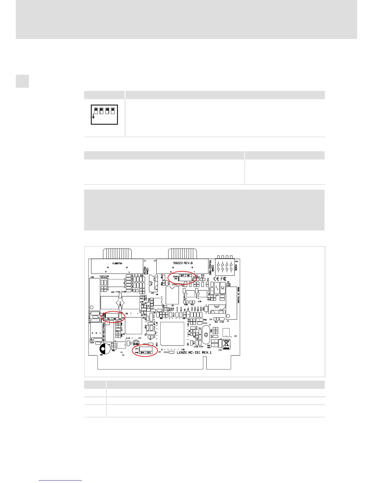
Further settings:
MC−ISI_003
Jumper Function
JP1 plugged−on to ENA: default setting
JP3 plugged−on to HW: default setting
JP5
plugged−on: terminating resistor for RS422−/485 mode activated
open: terminating resistor for RS422−/485 mode deactivated
Do not assign JP2! Lenze service personnel only.
 Loading...