Mechanical installation
Mounting of motors on gearboxes with mounting flange (drive-end version N)
Tightening torques
4
27
BA33.0001 EN 2.0
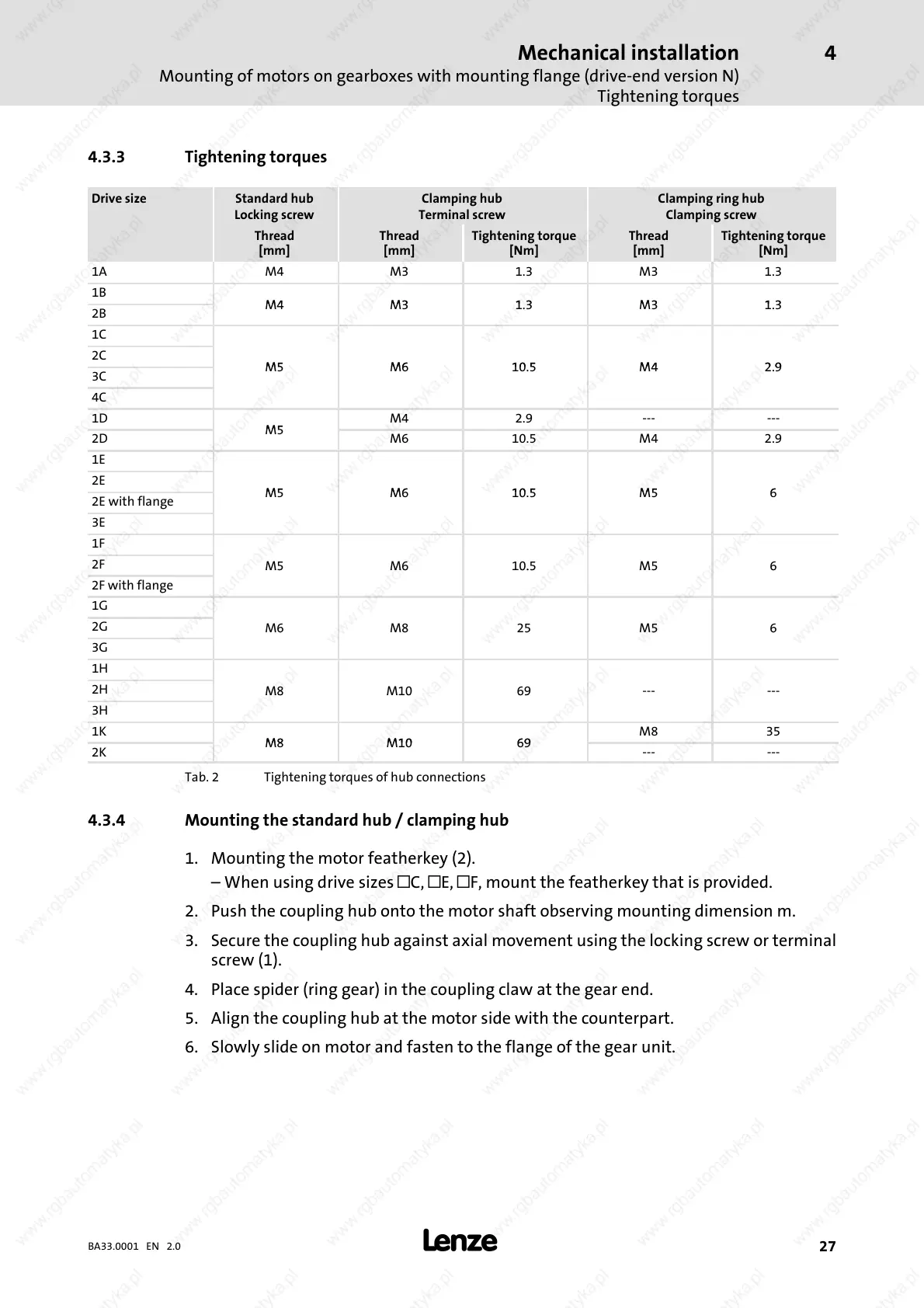
4.3.3 Tightening torques
Drive size Standard hub
Locking screw
Clamping hub
Terminal screw
Clamping ring hub
Clamping screw
Thread
[mm]
Thread
[mm]
Tightening torque
[Nm]
Thread
[mm]
Tightening torque
[Nm]
1A M4 M3 1.3 M3 1.3
1B
2B
M4 M3 1.3 M3 1.3
1C
2C
3C
M5 M6 10.5 M4 2.9
4C
1D
M4 2.9 --- ---
2D
M5
M6 10.5 M4 2.9
1E
2E
2E with flange
M5 M6 10.5 M5 6
3E
1F
2F
M5 M6 10.5 M5 6
2F with flange
1G
2G
M6 M8 25 M5 6
3G
1H
2H
M8 M10 69 --- ---
3H
1K
M8 35
2K
M8 M10 69
--- ---
Tab. 2 Tightening torques of hub connections
4.3.4 Mounting the standard hub / clamping hub
1. Mounting the motor featherkey (2).
– When using drive sizes
C,
E,
F, mount the featherkey that is provided.
2. Push the coupling hub onto the motor shaft observing mounting dimension m.
3. Secure the coupling hub against axial movement using the locking screw or terminal
screw (1 ).
4. Place spider (ring gear) in the coupling claw at the gear end.
5. Align the coupling hub at the motor side with the counterpart.
6. Slowly slide on m otor and fasten to the flange of the gear unit.
 Loading...