• Disconnect wires from screw terminals or
Quickwire™ slots (shown).
• Pull off pre-cut insulation from Dimmer
leads.
• Make sure that the ends of the wires
from the wall box are straight (cut if
necessary).
• Remove 5/8" (1.6 cm) of insulation from
each wire in the wall box (shown).
• For Single-Pole Application, go to Step
5A.
• For 3-Way Application, go to Step 5B.
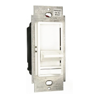
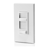
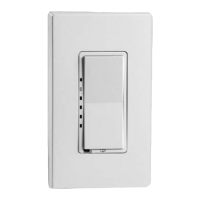
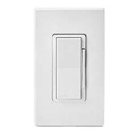
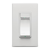
Single Pole (One location) or 3-Way (Multi-location)
Electronic Low-Voltage Slide Dimmer
Cat. No. 6615-P
300W–120VAC, 60Hz
INSTALLATION INSTRUCTIONS
DI-00X-06615-02B
Tools needed to install your Dimmer:
Slotted/Philips Screwdriver Electrical Tape
Pliers Pencil
Cutters Ruler
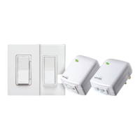
Installing Dimmer by itself or with other devices:
If installing Dimmer in a single device application, proceed with the
INSTALLING YOUR DIMMER section. If installing Dimmer in a multi-
device application, proceed as follows:
MULTI-DEVICE APPLICATION
In multi-dimmer installations, the reduction of the dimmerʼs capacity is
required. Refer to the chart for maximum load per dimmer.
MAXIMUM BULB WATTAGE
The maximum bulb wattage is determined by the efciency of the
transformer in the low-voltage lighting system. Transformer efciencies
will vary from different manufacturers; consider 80% efcient as average.
Use the chart to determine maximum bulb wattage for typical transformer
efciency ratings.
INSTALLING YOUR DIMMER
NOTE: Use check boxes when Steps are completed.
WARNING: To avoid re, shock, or death; TURN OFF
POWER at circuit breaker or fuse and test that power is off
before wiring!
Removing existing switch: Remove existing wallplate
and switch mounting screws. Carefully pull switch from wall
box. DO NOT remove wires attached to the switch at this time.
Identifying your wiring application (most
common):
NOTE: If the wiring in the wall box does not resemble any of
these congurations, consult a qualied electrician.
Step 2
Step 4
Step 1
Step 3
Single-Pole:
Look at the back of your
switch. If there are 2 wires
connected to two screw
terminals (not including a
green or bare copper wire
used for grounding), you
have a Single-Pole switch.
3-Way:
Look at the back of your switch. If there
are 3 wires connected to three screw
terminals (not including a green or bare
copper wire used for grounding), you
have a 3-Way switch. Note that one of
the screw terminals will usually be a
different color (black) or labeled
Common. Tag that wire with electrical
tape to identify.
WARNINGS:
• To be installed and/or used in accordance with appropriate electrical codes and regulations.
• If you are unsure about any part of these instructions, consult a qualied electrician.
• To avoid overheating and possible damage to this device and other equipment, do not install to control a
receptacle, uorescent lighting, a motor- or a transformer-operated appliance.
• Use with electronic low-voltage transformers only. Do Not use to control a magnetic low-voltage transformer.
Use a Leviton magnetic low-voltage dimmer to control magnetic low-voltage transformers.
• This dimmer provides protection from overheating. An excessive load applied to the dimmer will cause the
dimmer to overheat. The excess load must be removed to resume proper operation.
CAUTIONS:
• This dimmer requires a neutral wire connection. If a neutral wire is not in the wall box, consult a qualied electrician.
• Use only one (1) dimmer in a 3- or 4-way circuit. The switch(es) will turn the light on at the brightness level selected
at the dimmer.
• Lighting xture and dimmer must be grounded.
• Disconnect power at circuit breaker or fuse when servicing xture.
• Use this device only with copper or copper clad wire. With aluminum wire use only devices marked CO/ALR or
CU/AL.
√
More than
Cat. No. Single Two Devices 2 Devices
6615-P 300W 300W 250W
MAXIMUM LOAD PER DIMMER FOR MULTI-DEVICE
Tag Common
Screw Wire