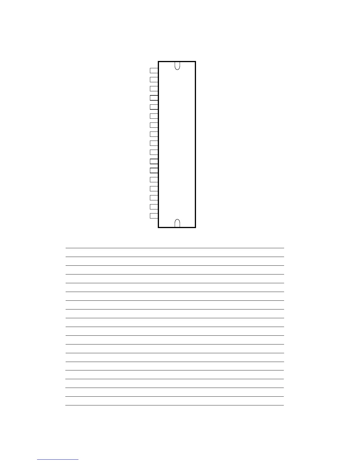
TDA8947J
5
Mode 2
4
OUT2-
3
V
CC1
2
GND1
1
OUT1+
6
IN2+
7
SGND
8
IN1+
9
IN3+
10
Mode 1
11
SVR
12
IN4+
13
CIV
14
OUT3-
15
GND2
16
V
CC2
17
OUT4+
Table 3: Pin description
Symbol Pin Description
OUT1+ 1 non inverted loudspeaker terminal 1
GND1 2 ground channel 1
V
CC1
3 supply voltage channel 1
OUT2- 4 inverted loudspeaker terminal 2
Mode 2 5 mode selection of subwoofer (channel 3/4)
IN2+ 6 input 2
SGND 7 signal ground
IN1+ 8 input 1
IN3+ 9 input 3
Mode 1 10 mode selection input (standby, mute, operating)
SVR 11 half supply voltage decoupling (ripple rejection)
IN4+ 12 input 4
CIV 13 Common input voltage decoupling
OUT3− 14 inverted loudspeaker terminal 3
GND2 15 ground channel 2
V
CC2
16 supply voltage channel 2
OUT4+ 17 non inverted loudspeaker terminal 4
 Loading...