EasyManua.ls Logo

LG MULTI V ARUN***CTE4 User Manual

LG MULTI V ARUN***CTE4
83 pages
To Next Page IconTo Next Page
To Previous Page IconTo Previous Page
Page #69 background image
ELECTRICAL WIRING
69
ENGLISH
Example) Group number setting
1
st
number indicate the group number
2nd number point out indoor unit number
SODU.B SODU.A IDU.B IDU.A CEN.B CEN.A DRY1 DRY2 GND 12V
B(D) A(C) BA
1 F
Group Indoor unit
Group recognizing the central controller
No.0 group (00~0F)
No.1 group (10~1F)
No.2 group (20~2F)
No.3 group (30~3F)
No.4 group (40~4F)
No.5 group (50~5F)
No.6 group (60~6F)
No.7 group (70~7F)
No.8 group (80~8F)
No.9 group (90~9F)
No. A group (A0~AF)
No. B group (B0~BF)
No. C group (C0~CF)
No. D group (D0~DF)
No. E group (E0~EF)
No. F group (F0~FF)
Group Number setting
Group Number setting for Indoor Units
- Confirm the power of whole system(Indoor Unit, Outdoor Unit) is OFF, otherwise turn off.
- The communication cables connected to CEN.A and CEN.B terminal should be connected to
central control of Outdoor Unit with care for their polarity (A-A, B-B ).
- Turn the whole system on.
- Set the group and Indoor Unit number with a wired remote control.
- To control several sets of Indoor Units into a group, set the group ID from 0 to F for this pur-
pose.
Outdoor Units (External PCB)
Question and Answer IconNeed help?

Do you have a question about the LG MULTI V ARUN***CTE4 and is the answer not in the manual?

LG MULTI V ARUN***CTE4 Specifications

General IconGeneral
BrandLG
ModelMULTI V ARUN***CTE4
CategoryAir Conditioner
LanguageEnglish

Summary

Tips for Saving Energy

For Your Records

Section to record purchase details for warranty purposes.

Important Safety Instructions

Installation Safety Precautions

Precautions and guidelines for safe installation procedures.

Operation Safety Guidelines

Guidelines for safe operation of the air conditioner.

Installation Process Overview

Outdoor Units Information

ARUN***CTE4 Model Specifications

Technical specifications for outdoor units of the ARUN***CTE4 model series.

Alternative Refrigerant R410A

Select the Best Location

Installation Space Requirements

Individual Installation Space

Minimum space requirements for individual unit installation.

Seasonal Wind and Winter Cautions

Advisories for installation in areas with seasonal winds and winter conditions.

Lifting Method

Installation Guidelines

Anchor Bolt Location and Specifications

Specifies the correct placement and dimensions for anchor bolts.

Outdoor Unit Foundation

Guidelines for creating a stable and secure foundation for the outdoor unit.

Preparation of Piping

Flare Connection and Tightening

Pipe Connection Precautions

Important considerations for connecting flare nuts and pipes safely.

Shutoff Valve Operation

Procedure for safely opening and closing shutoff valves.

Plumbing Materials and Storage

Refrigerant Piping Principles

Three key principles for refrigerant piping: Drying, Cleanliness, and Airtightness.

Nitrogen Substitution Method

Refrigerant Piping Installation

Pipe Connection and Valve Operation Precautions

Safety guidelines for connecting pipes and operating valves.

Pipe Connections: Indoor and Outdoor Unit

Preparation for Pipe Connections

Steps to prepare for connecting pipes, including using knock-outs.

Pipe Drawing Out Methods

Procedures for drawing out pipes from the unit for connection.

Bottom Side Pipe Drawing Out

Specific method for drawing pipes from the bottom side of the unit.

Refrigerant Piping System Configurations

Y Branch Piping System

Explains the Y branch method for refrigerant piping systems.

Refrigerant Pipe Diameter Selection

Guidelines for selecting refrigerant pipe diameters based on capacity.

Header Piping System

Explains the header method for refrigerant piping systems.

Combined Y Branch and Header Methods

Details on combining Y branch and header methods for piping.

Outdoor Unit Connection Procedures

Indoor Unit Connection

How to connect indoor units to the outdoor unit.

Branch to Indoor Unit Pipe Connection

Specifics on connecting pipes from branches to indoor units.

Series Outdoor Unit Pipe Connections

Series Connection Methods and Examples

Illustrates various methods and precautions for series outdoor unit connections.

Common Pipe Connection Errors

Highlights common mistakes in pipe connections to avoid.

Refrigerant Amount Calculation

Refrigerant Charging Procedure

Piping Distribution Methods

Horizontal Distribution

Illustrates horizontal distribution methods for refrigerant piping.

Vertical Distribution

Illustrates vertical distribution methods for refrigerant piping.

Other Distribution Configurations

Covers alternative distribution configurations for piping.

Branch Pipe Fitting

Y Branch Fitting Details

Details on fitting Y branches for refrigerant piping.

Header Fitting Details

Details on fitting headers for refrigerant piping.

Leak Test and Vacuum Drying

Leak Test Procedure

Steps for performing a leak test using nitrogen gas.

Vacuum System Drying

Vacuum Drying Procedure

Method for performing vacuum drying of the refrigeration system.

Vacuum Mode Operation

Setting the Vacuum Mode

Steps to set and activate the vacuum mode.

Disabling Vacuum Mode

Procedure to disable the vacuum mode.

Thermal Insulation of Refrigerant Piping

Electrical Wiring

Power Wiring Best Practices

Guidelines for safely laying power wiring.

Control Box and Wiring Connections

Location of control boxes and how to connect wiring.

Communication and Power Cable Separation

Information on communication and power cables and their separation.

Main Power Supply and Capacity Wiring

Wiring requirements for main power supply and capacity.

Field Wiring Configurations

Communication Cable Connection Example

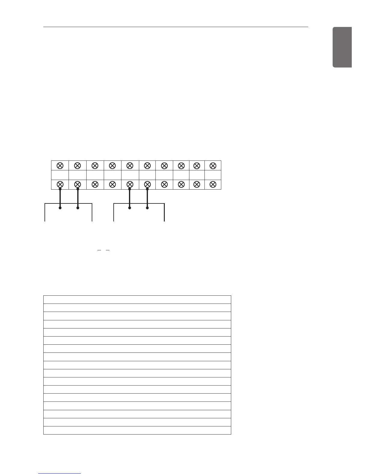
Example of connecting communication cables for field wiring.

Two Outdoor Unit Wiring (3Ø, 575V)

Wiring configuration for two outdoor units.

Three Outdoor Unit Wiring (3Ø, 575V)

Wiring configuration for three outdoor units.

Outdoor Unit Setting Check

Dip Switch Setting Verification

How to check and set outdoor unit configurations using dip switches.

Initial Display Interpretation

Understanding the initial display on the 7-segment LED.

Automatic Addressing of Indoor Units

Automatic Addressing Procedure

Steps for automatically addressing indoor units.

Function Setting and Modes

Group Number Setting for Indoor Units

Indoor Unit Group Number Configuration

How to set group numbers for indoor units.

Test Run Procedures

Cool & Heat Selector Mode

Setting the cooling and heating modes.

Static Pressure Compensation Mode

Adjusting static pressure for optimal airflow.

Night Low Noise Function

Enabling a mode to reduce fan noise at night.

Overall Defrost Mode Setting

Setting the defrost mode for the unit.

Outdoor Unit Address Setting

Assigning addresses to outdoor units.

Snow Removal & Rapid Defrost Modes

Configuring modes for snow removal and rapid defrost.

Target Pressure Adjusting

Adjusting target pressure for performance optimization.

Self-Diagnosis Function and Errors

Error Indicator and Display Interpretation

Explains error codes and their meanings.

Refrigerant Leak Caution and Safety

Introduction to Refrigerant Safety

General information on refrigerant safety and limiting concentrations.

Limiting Refrigerant Concentration

Defines the safe limit for refrigerant gas concentration.

Refrigerant Concentration Check Procedure

Steps to check and manage refrigerant concentration.

Countermeasures for High Concentration

Actions to take when refrigerant concentration exceeds safety limits.

Installation Guide for Seaside Locations

Seaside Location Selection Criteria

Guidelines for choosing an appropriate location near the seaside.

Related product manuals