System Engineering
66
|
SYSTEM ENGINEERING
Due to our policy of continuous product innovation, some specifications may change without notification.
© LG Electronics U.S.A., Inc., Englewood Cliffs, NJ. All rights reserved. “LG” is a registered trademark of LG Corp.
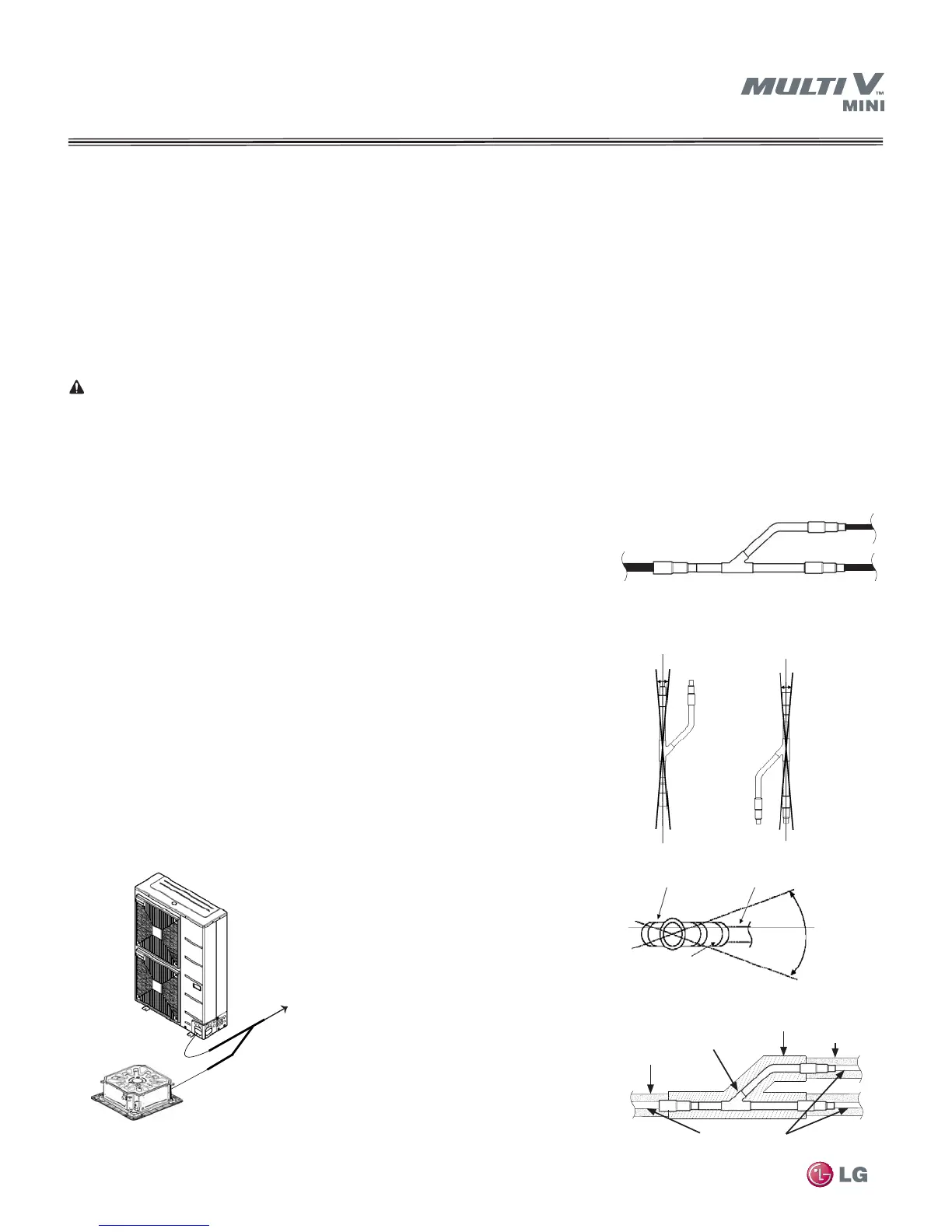
Figure 36: Connecting Y-Branch Kits
PIPING DESIGN GUIDE
General:
The Y-Branch and Header kits are used to join one pipe segment to two or more segments. See Cut-Sheets: "Y-Branch Kits" on page 80
and "Header Kits" on page 81 for sizes and dimensions.
a. Vertical Up
Confi guration
b. V
ertical Down
Confi guration
c. Horizontal Confi guration End View
LG Engineered Y-Branch and Header Kits
LG Y-Branch kits consists of:
• Two Y-Branches (one liquid line, one vapor line)
• Reducer fi ttings as applicable
• Molded clam-shell type insulation covers
LG Header kits consists of:
• Two Headers (one liquid line, one vapor line)
• Reducer fi ttings as applicable
• Molded clam-shell type insulation covers
Y-Branch Kits
Y-Branch Insulation
Each Y-Branch kit comes with two clam-shell
type peel and stick insulation jackets molded to
fit the Y-Branch fittings as shown in Figure 39—
one for the liquid line, one for the vapor line.
1. Check the fi t of the Y-Branch clam-shell insula-
tion jacket after the Y-Branch is installed.
2. Verify there will be no exposed pipe between
the end of the Y-Branch, jacket, and adjacent
pipe insulation.
3. Mark the pipe where the insulation jacket ends.
4. Remove the jacket.
Note: Only LG supplied Y-Branch
and Header fittings can be used
to join one pipe segment to two or
more segments.
LG Y-Branch and Header kits
are precision engineered devices
designed to evenly divide the flow
of refrigerant. Third-party or field
fabricated Tee’s, Y-fittings, Head-
ers, or other branch fittings are not
qualified for use with LG Multi V
systems. The only field-provided
fittings allowed in a Multi V piping
system are 45° and 90° elbows
and full-port ball valves.
There is no limitation on the
number of Y-Branches that can
be installed, but there is a limita-
tion on the number of indoor units
connected to a single outdoor unit.
See Table 1a on page 14.
Avoid installing Y-Branches back-
wards as shown in Figure 36. Re-
frigerant fl ow cannot make U-turns
through Y-Branches.
The pipe coming from the outdoor unit should
always connect to the single port end of the
Y-Branch as shown in Figure 37.
Y-Branches may be installed in a horizontal
or vertical configuration. When installed
in the horizontal configuration, position the
fitting so the take-off leg shares the same
horizontal plane as the straight-thru leg ±10
°
as shown in Figure 38c. When installed in
a vertical configuration, position the fitting
so the straight-thru leg is ±3° of plum. See
Figure 38 (a and b).
The first Y-Branch kit must be located at
least 3 feet from the outdoor unit. Provide a
minimum of 20 inches between a branch fit-
ting and any other fitting or indoor unit piped
in series to avoid generating refrigerant flow
noise into the system.
It is recommended that when a Y-Branch is
located in a pipe chase or other concealed
space, access doors should be provided for
access and inspection.
See "Refrigerant Pipe System Insulation"
on page 76 for pipe system insulation
information.
5. Install fi eld-provided insulation on the 3
pipes fi rst.
6. Peel the adhesive glue protector slip and
install the clam-shell jacket over the fi tting.
To ODU
To IDU
To IDU
-3° +3°
-3° +3°
Straight Through Leg Branch Leg
10°
-10°
Horizontal Plane
Y-Branch Inlet
Field-Supplied Insulation
LG-Supplied Y-Branch Fitting
LG-Supplied Insulation Jacket
Field-Supplied Insulation
Field-Supplied Copper Pipe
To next branch
To indoor unit
Figure 37: Y-Branch Connections
Figure 38: Y-Branch insulation alignment
specification
Figure 39: Y-Branch insulation and pipe
detail
 Loading...