13
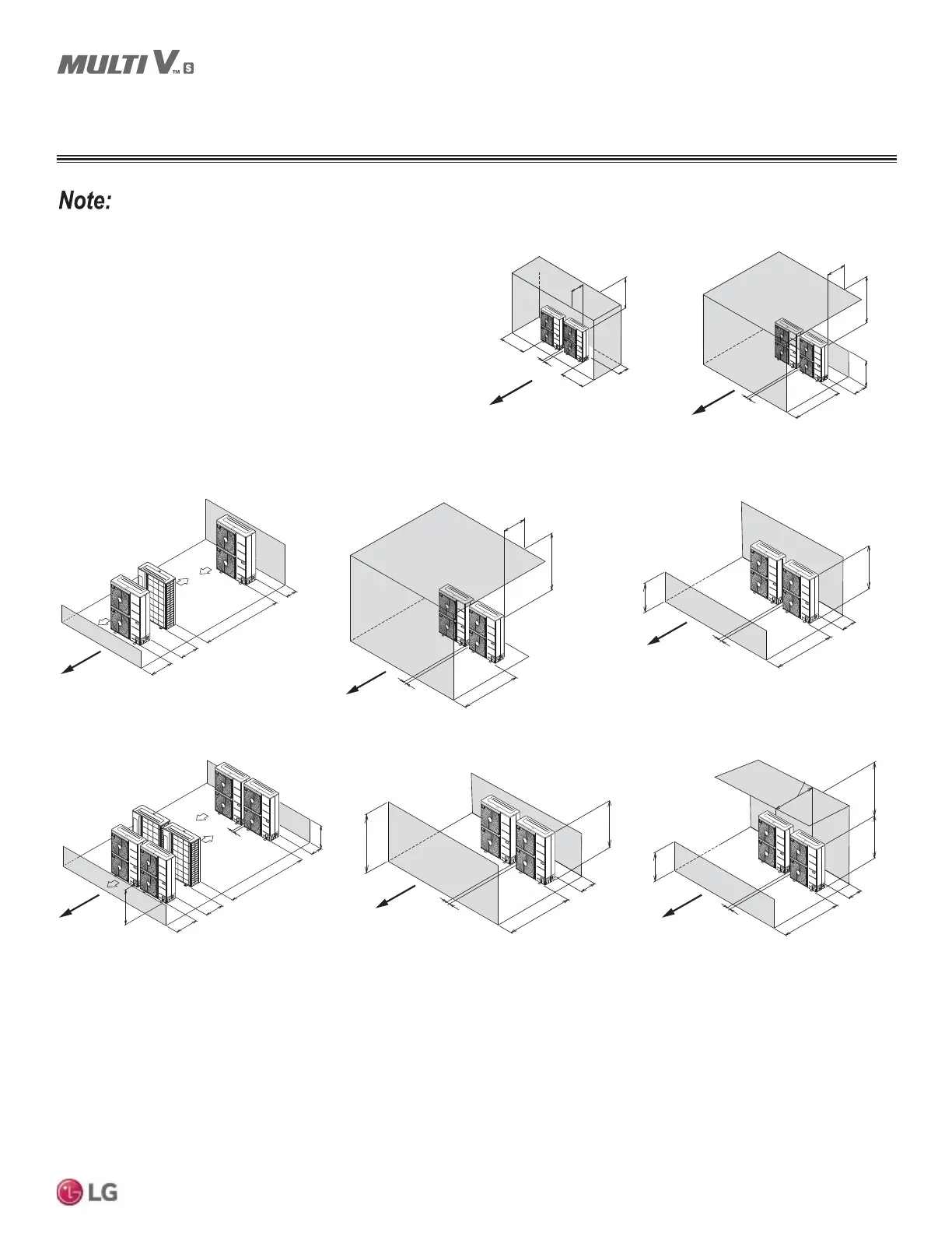
General Installation Guidelines
Due to our policy of continuous product innovation, some specifications may change without notification.
©LG Electronics U.S.A., Inc., Englewood Cliffs, NJ. All rights reserved. “LG” is a registered trademark of LG Corp.
Max. 20"
Min. 40"
Min. 40"
Min. 4"
Min. 8"
Min. 12"
LR < H
Min. 40"
Min. 50"
Max. 20"
Min. 4"
Min. 12"
Side by Side—High Rear and Side
Walls with Building Overhang
Side by Side—High Rear and Front Walls
with Building Overhang
A
i
r
o
w
A
i
r
o
w
LR
Min. 40"
Min. 8"
Min. 79"
Min. 4"
LF
H
Min. 59"
Min. 12"
Min 4"
Min. 40"
Min. 40"
Max. 20"
Min. 12"
Min. 12"
Min. 119"
Min. 24"
Min. 59"
Min. 4"
LR H
Min. 59"
Min. 12"
Min 4"
LF
H
Min. 59"
Min. 12"
Min 4"
Min. 40"
Max. 20"
Single Row Units—High Rear Wall and Low Front Wall with
No Side Walls or Overhang
Side by Side —High Front Wall with Building Overhang
and No Side or Rear Walls
Side by Side—High Rear Wall and Low Front Wall with No Side Walls
Double Row Units—Low Rear and Front Walls with No Side
Walls or Overhang
Side by Side—High Front and Rear Walls with No Side Walls Side by Side—High Rear Wall and Low Front Wall with Building
Overhang and No Side Walls
A
i
r
o
w
A
i
r
o
w
A
i
r
o
w
A
i
r
o
w
A
i
r
o
w
A
i
r
o
w
LF
H
H
LR
LF > H
LF
H
LF
H
Legend
LR = Rear wall height
LF = Front wall height
H = Unit height
• Installation clearances must comply with local building codes.
• All figures not to scale.
Figure 6: Proper Outdoor Unit Placement and Clearances, continued.
Figure 7: Proper Outdoor Unit Placement and Clearances, continued.
Service Access and Allowable Clearances for Outdoor Unit
GENERAL INSTALLATION GUIDELINES

 Loading...