TERMOTRONIC™ controllers
8 Air-to-Water Heat Pump
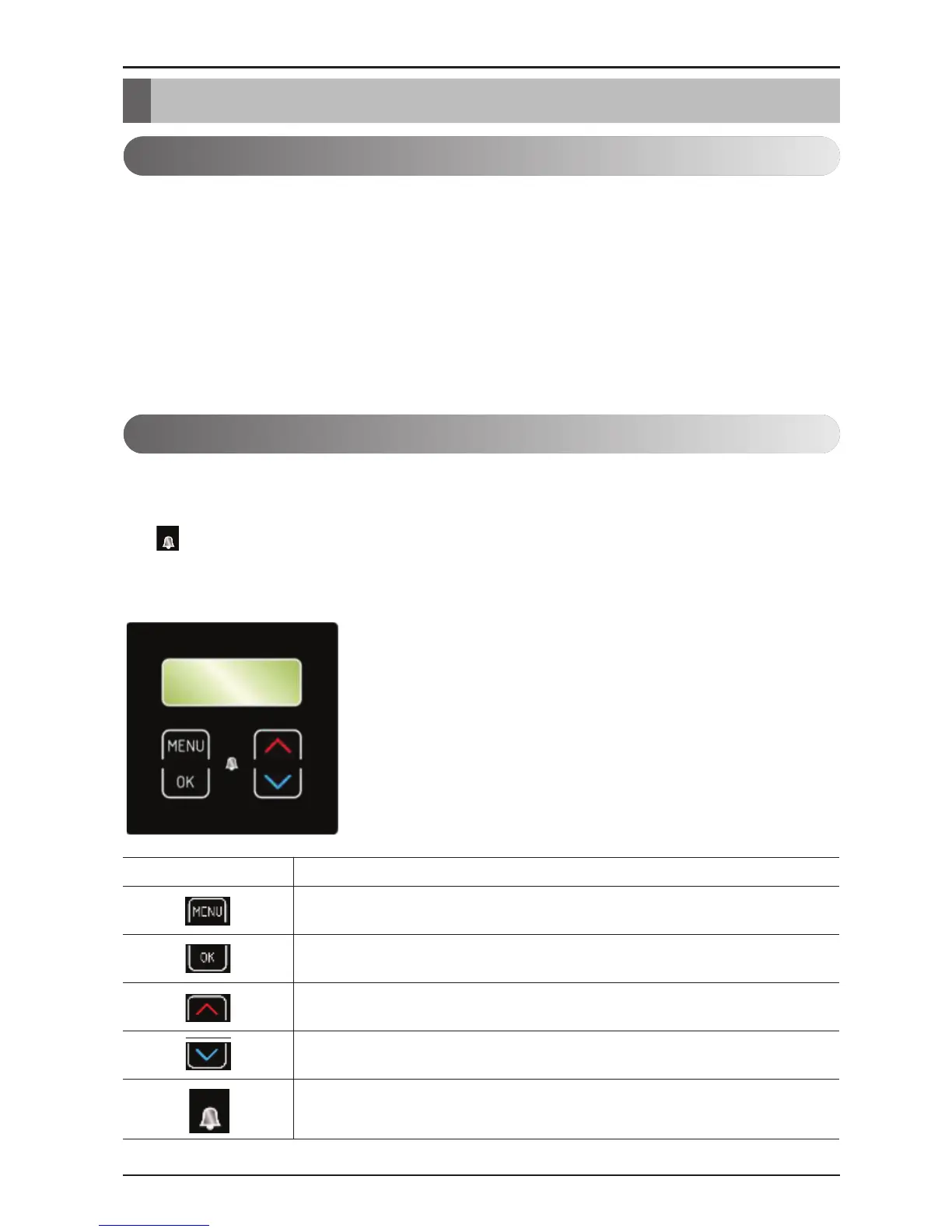
Controlling the device and heating system
The device and heating system can be controlled with the use of 4 buttons on the controller interface
TERMOTRONICTM. The controller interface has a 4-line LCD screen which displays the current
state of the device or controller and a LCD light indicator of malfunctions in the operation of the
device (ALARM).
The controller interface TERMOTRONICTM in devices:
BUTTON BUTTON FUNCTION
MENU: Scrolling through the main menu and sub-menus.
ENTER: On, off, accessing the menu, accessing the settings and confirm-
ing selected values.
»+«: Selecting the values, scrolling up the menus and sub-menus.
»-«: Selecting the values, scrolling down the menus and sub-menus.
ALARM: Indicator of device malfunction.
General
TERMOTRONIC™ is a self-adapting controller for controlling the heat pump (hereinafter the
DEVICE) and the heating system. It controls the operation of the device so as to ensure the most effi-
cient way to produce the desired temperature of the building based on the needs of the heating sys-
tem and outside temperature.
The TERMOTRONIC™ controller offers controlling of the device and the heating system of the build-
ing (no more than 4 heating circuits) as well as controlling the heating with an alternative heat
source, active cooling with the device, heating DHW with the device and/or alternative heat source
and/or backup source.
TERMOTRONIC™ controllers
 Loading...