Quick Start Guide
UMX-TPS-TX120
UMX-TPS-TX130
UMX-TPS-TX140
UMX-TPS-TX140-Plus
Further information
The document is valid with the following rmware version: 1.3.0
The User’s manual of this appliance is available on www.lightware.com.
See the Downloads section on the dedicated product page.
Contact us
sales@lightware.com
+36 1 255 3800
support@lightware.com
+36 1 255 3810
Lightware Visual Engineering LLC.
Peterdy 15, Budapest H-1071, Hungary
Doc. ver.: 2.3
19200131
Rear Panel LEDs
LIVE
OFF: the device is not powered.
BLINKING (slow): the device is powered and operational.
BLINKING (fast): the device is in bootload mode.
ON: the device is powered but no operation.
RS-232
OFF: RS-232 ports (Local and Link) are in Pass-through mode.
BLINKING: Command Injection mode is active.
ON: RS-232 ports (Local and Link) are in Control mode.
SRVC
ON: Test pattern is the selected and active input source.
LINK
OFF: no TPS link between transmitter and receiver.
BLINKING (slow): low power mode is active.
BLINKING (fast): Ethernet fallback mode is active.
ON: TPS link is established, HDBaseT or Long reach mode is active.
* Only on UMX-TPS-TX130, UMX-TPS-TX140, and UMX-TPS-TX140-Plus
** Only on UMX-TPS-TX140 and UMX-TPS-TX140-Plus
Front Panel LEDs (UMX-TPS-TX-140)
Video Sources
OFF: video source is not selected.
BLINKING: video source is selected
but not active.
ON: video source is selected and active.
Audio Sources
OFF: audio source is not selected.
BLINKING: audio source is selected
but not active.
ON (with short pause): audio source is selected and the port is active but not embedded
to the output video stream (DVI output mode).
ON (continuously): audio source is selected, the port is active and the audio is embedded
to the output video stream (HDMI output mode).
HDCP LED
OFF: video output signal is not encrypted with HDCP.
ON: video output signal is encrypted with HDCP.
Autoselect LED
OFF: autoselect is disabled.
BLINKING: autoselect is enabled; searching for signal (video LEDs also blink).
ON: autoselect is enabled; active video signal is found (the LED of selected video also lights).
A port is active if there is a valid signal on it.
Important Safety Instructions
Please read the supplied safety instruction document before using the product and keep it
available for future reference.
Introduction
Lightware’s UMX-TPS-TX100 devices transmit universal video at a resolution up to 4K, audio
and control up to 170 m distance over a single CAT cable. The products have HDBaseT
TM
integration with additional Lightware developments. The transmitter was designed for digital
and analog video and audio signals e.g. DVI, VGA, HDMI1.4 and DP 1.1 with analog stereo
audio from local inputs or embedded 7.1 HBR audio and to handle HDCP encryption.
The UMX-TPS-TX140-Plus model offers advanced control features: 100 available event slots;
support RS-232 protocol for communication and control of third party devices like VC codec
- this allows the Cisco Room Kit login on RS-232–USB connection; support to receive CEC
commands for control of displays and Lightware Event Manager to automate room actions;
support to send CEC commands on HDMI ports for control of other devices; support true
Infrared messages using HEX codes to control TVs, media players and other devices with
IR emitters.
Compatible Devices
The transmitters are compatible with other Lightware TPS
devices, matrix TPS and TPS2 boards, 25G boards, as
well as third-party HDBaseT
TM
extenders, displays, but not
compatible with the phased out TPS-90 extenders.
HDBaseT
TM
and the HDBaseT Alliance logo are trademarks of the HDBaseT Alliance.
Box Contents
Transmitter unit 12V DC power adaptor
with interchangeable plugs
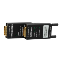
Infrared transmitter unit
Phoenix combicon
3-pole connector
Phoenix combicon
8-pole connector**
Phoenix combicon
5-pole connector*
Safety and warranty info,
Quick Start Guide
* Only for UMX-TPS-TX140 and UMX-TPS-TX140-Plus
** Only for UMX-TPS-TX130, UMX-TPS-TX140, and UMX-TPS-TX140-Plus
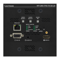
Front View Legend (UMX-TPS-TX140)
1
VGA Input Input for an analog video source. Using a VGA cable where
all the pins are wired (DDC channel) is highly recommended.
2
Audio Input 3.5 mm Jack connector for unbalanced analog audio signal.
3
HDMI Input Input for a digital video source. Applied cable shall not be
more, than 30 m (at 1080p) and 15 m (at 4K).
4
DisplayPort
Input**
Input for digital video source (only on TX140 models). Applied
cable shall not be more, than 30 m (at 2.7 Gbps data speed).
5
Status LEDs The LEDs give feedback about the state of the unit, the
video and audio signals. See the attached list for details.
6
Video/Audio Select Selecting a video/audio input manually.
7
Reset Button The same as disconnecting the device from the power
source and reconnecting it again.
8
Show me Button Special functions are available with this button (e.g. enable
DHCP or restore factory default settings).
Rear View Legend (UMX-TPS-TX140)
1
12V DC Input
connector
12V DC input for local powering.
2
RS-232 connector 3-pole Phoenix connector for RS-232 serial port.
3
GPIO* 8-pole Phoenix connector for congurable general purpose
input/output ports.
4
Ethernet Locking RJ45 connector for Ethernet communication.
5
TPS Output Port Locking RJ45 connector for HDBaseT
TM
signal transmission.
Connect a twisted pair cable between the transmitter and the
receiver.
6
Status LEDs The LEDs give feedback about the actual state of the device.
7
IR Input/Output 2 TRS (3.5mm jack) connectors for Infrared units (IR IN for the
detector, IR OUT for the emitter).
8
Audio Input** 5-pole Phoenix connector for unbalanced analog audio signal.
9
DVI-I Input* DVI-D or DVI-A signal input port.
Power Supply Options
The transmitters can be powered:
Locally with the supplied 12V DC adaptor or Lightware’s rack mountable PSU, or
Remotely by a PoE-compatible power injector, like Lightware’s TPS-PI-1P1.
Powering by a matrix board over the TPS (CATx) cable. Output board needs to be
powered by an external PSU.
UMX-TPS-TX100 transmitters are PoE-compatible and can receive power over the TPS
line. The TPS-TX/RX95 extenders are not PoE-compatible thus not able to send/receive
power to/from the UMX-TPS-TX100 transmitters.
Connecting Steps
Locking DC plug
Twist 90° clockwise to lock.
Mounting
To mount the device Lightware supplies optional accessories for different usage. There are
two kinds of mounting kits with similar xing method. The transmitter has two mounting holes
with inner thread on the bottom side. Fasten the device by the screws enclosed with the
accessory.
The Under-desk double mounting kit makes it easy to mount a single device on any at
surface, e.g. furniture. 1U high rack shelf provides mounting holes for fastening two half-rack
or four quarter-rack sized units. Pocket-sized devices can also be fastened on the shelf. To
order mounting accessories please contact sales@lightware.com.
Using different (e.g. longer) screws may cause damage to the device.
The transmitter is half-rack sized.
Under-desk double mounting kit 1U high rack shelf
Connect the TPS output port to the TPS+PoE output port of the
TPS-PI-1P1 by a CATx cable.
Connect the receiver (or the Matrix input board) to the power injector by a
CATx cable via the TPS port.
HDMI
DP
Connect the transmitter and the sources using the inputs and VGA /
DisplayPort / HDMI / DVI-I / cables.
Optionally for audio extension: connect the audio source (e.g. media player)
to the audio input port by an audio cable.
Optionally connect the transmitter to a LAN in order to control the device.
Optionally connect a controller/controlled device (e.g. relay box) to the GPIO port.
Optionally connect a serial device to the transmitter’s RS-232 port.
Optionally for Infrared extension:
Connect the IR emitter to the IR OUT port of the switcher, and/or
Connect the IR detector to the IR IN port of the switcher.
Powering on the devices is recommended to do as the nal step during the
installation. Please see the Power Supply Options section for the details.
VGA
HDMI
DP
DVI-D
Audio1
HDMI
DP
DVI-D
HDCP
Autoselect
DVI-A Video
Audio2
VGA
HDMI
DP
DVI-D
Audio1
HDMI
DP
DVI-D
HDCP
Autoselect
DVI-A Video
Audio2
PIN: 2.1mm
GPIO
RS-232
TX RX
AUDIO2 IN
DVI-I IN
IR IN IR OUT
LIVE
RS-232
SRVC
LINK
12V 1A DC
PIN: 2.1mm
GPIO
RS-232
TX RX
AUDIO2 IN
DVI-I IN
IR IN IR OUT
LIVE
RS-232
SRVC
LINK
12V 1A DC
TPS-PI-1P1
48 DC IN
Typical: 0.7A
Max: 1.5A
- +
Max:2.5A
PIN: 2mm
CATx
(TPS)
Power
send
48V DC
Power
adaptor
PIN: 2.1mm
GPIO
RS-232
TX RX
AUDIO2 IN
DVI-I IN
IR IN IR OUT
LIVE
RS-232
SRVC
LINK
12V 1A DC
12V DC
Power
adaptor
MX-TPS2-IB-P
DC IN
8 CH TPS INPUT BOARD WITH POE
48V 5A
- +
Ethernet
TPS IN 1 TPS IN 2 TPS IN 3 TPS IN 4
8CH INPUT BOARD FOR HDMI WITH 3D AND ANALOG AUDIO
MX-HDMI-3D-IB-A
IN 1
IN 2
IN 3
IN 4
MX-TPS2-OB-S
48V 5A
DC IN
8 CH TPS OUTPUT BOARD WITH DIGITAL AUDIO
12V power on TPS connector. Only use with compatible devices!
12V power on TPS connector. Only use with compatible devices!
TPS OUT 1 TPS OUT 2 TPS OUT 3 TPS OUT 4
8CH OUTPUT BOARD FOR HDMI WITH 3D AND ANALOG AUDIO
MX-HDMI-3D-OB-A
OUT 1
CATx
(TPS)
External
power supply
Power
send
RS-232
Audio
DVI-I
GPIO
Laptop
VGA
Blu-ray player
HDMI
DP
Mac
Media player
IR
Ethernet InfraredRelay box
LAN
Touch panel
PC
UMX-TPS-TX140
Power
Compatible
TPS Receiver
CATx
VIDEO AUDIO
DVI-A Video
Autoselect
HDCP
Audio2
DVI-D
DP
DVI-D
DP
SHOW
ME
AUDIO
SELECTINPUT STATUS
VIDEO
SELECT
HDMI HDMI
VGA
Audio1
RESET
AUDIO1 IN HDMI IN DP IN VGA IN
Safety and
Warranty
Info
Quick
Start
Guide