2
TOOLS REQUIRED
The fi nish-out installation should be made after the
application of any wall covering material.
The tools required for the installation fi nish-out are:
• #2 Phillips screwdriver
• Standard fl at head screwdriver
• Wire stripper/cutter
•Level
ROOM STATION INSTALLATION
1. Collect all the connectors included in the Room Station packages and
place them in the wall housing for use later.
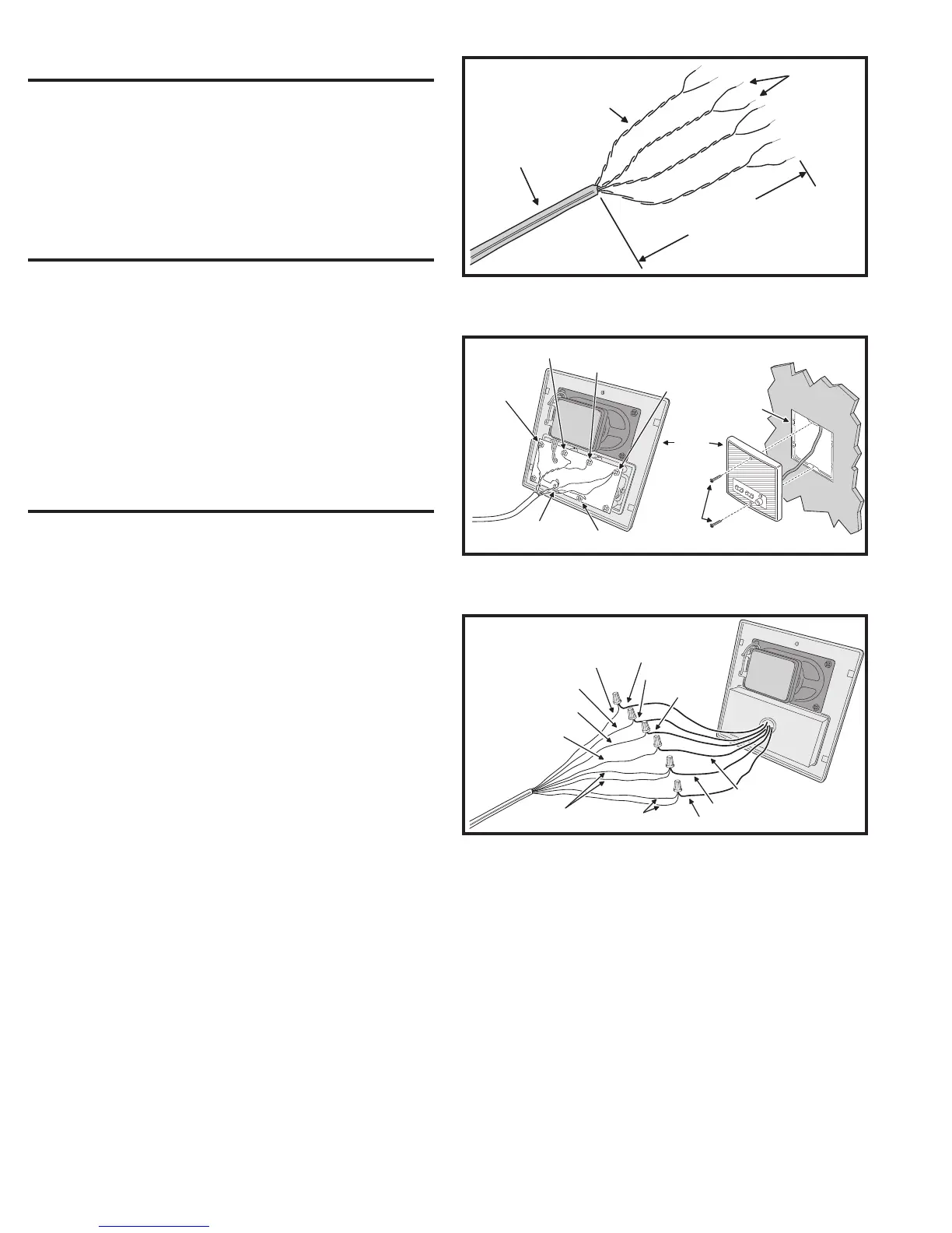
2. At each Room Station location, strip approximately 4 inches of jacket
from the Cat-5 cable and separate the colored wires. Strip 1/2 inch of
insulation from each wire as shown in Figure 2.
3. Connect each colored wire to its respective screw terminal in the
Room Station. Note that some screw terminals have more than one
wire connected to them.
4. Mount each Room Station to its mounting ring using the two screws
provided with each DMC1 Room Station as shown in Figure 3.
PATIO STATION INSTALLATION
Use wire nuts for the following connections.
1. At each Patio Station location, strip approximately 4 inches of jacket
from the Cat-5 cable and separate the colored wires. Strip 1/2 inch of
insulation from each wire as shown in Figure 2.
2. Connect ORANGE wire to the ORANGE wire on the Patio Station.
3. Connect BLUE wire to the BLUE wire on the Patio Station.
4. Connect ORANGE/WHITE wire to the ORANGE/WIRE wire on the
Patio Station.
5. Connect GREEN/WHITE wire to the GREEN/WIRE wire on the Patio
Station.
6. Connect GREEN and BROWN/WHITE wires to the GREEN wire on
the Patio Station.
7. Connect BROWN and BLUE/WHITE wires to the BROWN wire on
the Patio Station.
8. Mount the Patio Station to the housing using the two screws provided
with the Patio Station.
Figure 2. Cat-5 Wire Preparation
CAT-5 CABLE
STRIP CABLE JACKET
BACK 4 INCHES
STRIP EACH
WIRE BACK
MAXIMUM
1/2 INCH
KEEP CABLE
PAIRS TWISTED
TO REDUCE HUM
Figure 3. Attaching Room Station
MOUNTING
RING
ROOM
STATION
MOUNTING
SCREWS
GREEN / WHITE
ORANGE / WHITE
ORANGE
BROWN &
BLUE / WHITE
BLUE
GREEN &
BROWN / WHITE
CONNECT
CAT-5
WIRES
CAT-5
Figure 4. Patio Station Wiring Connections
ORANGE
BLUE
ORANGE / WHITE
GREEN / WHITE
GREEN &
BROWN / WHITE
BROWN &
BLUE / WHITE
GREEN
BROWN
PATIO
STATION
CAT-5
ORANGE
BLUE
ORANGE / WHITE
GREEN / WHITE
 Loading...