4
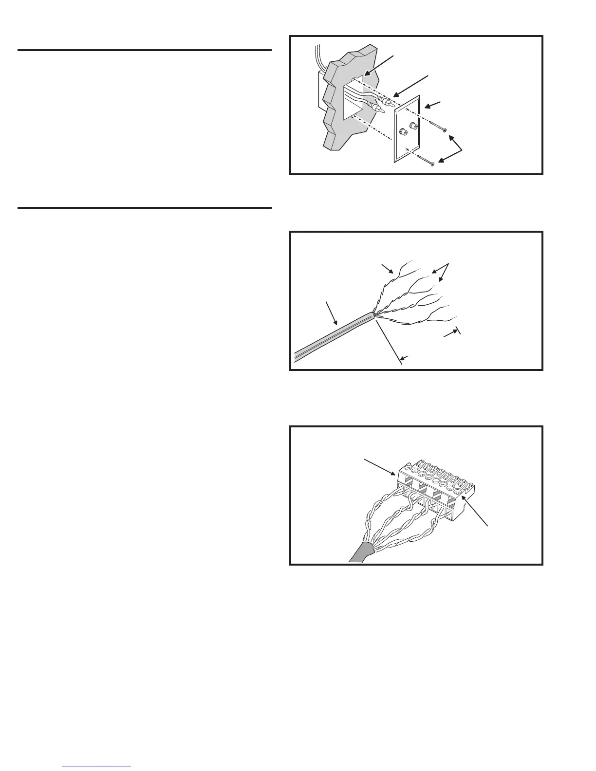
EXTERNAL MUSIC SOURCE
The DMC1 Master Station can play audio from an external
source. A commonly available audio input wall plate with a
pair of stereo RCA jacks can be wired to the DMC1 Master
Station and connected to a stereo receiver, television, DVD,
or portable music player.
1. At the location for the audio input wall plate, access the left and right
audio cables that were routed to the J-box during the system rough-in.
2. Connect the RCA plugs to each of the RCA jacks on the rear of the
wall plate.
3. Tuck the cables into the J-box and attach the audio input wall plate
to the J-box.
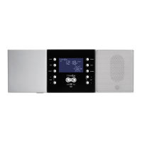
INTERCOM MASTER STATION INSTALLATION
The DMC1 Master Station connects to the room, patio, and
Door Station wires at the wall housing location. All other
connections to the Master Station are also made at the wall
housing location.
To ensure good electrical and mechanical connections, and
to avoid service call-backs, refer to the following steps and
the associated fi gures when terminating wires. Stations are
supplied with screw-down Cat-5 connectors, press-on type
Cat-5 connectors may also be included.
Screw-down Connector Cable Termination
1. Gather all room, patio, and Door Station cables together and cut them
to the same length leaving approximately 12 inches entering into the
wall housing. BE SURE THAT THE CABLES REMAIN LABELED.
✔ IMPORTANT: Verify all cable run locations prior to connecting if they
were not labeled at rough-in. Incorrectly connecting cables to the
Master Station, Room Stations, or Door Stations may result in system
damage.
2. Strip back the outer insulation jacket of the room and Patio Station
Cat-5 cables 2 inches to expose the four color coded twisted wire
pairs inside. Strip back each of the eight wires 1/4” maximum (see
Figure 8).
3. Observing the color code label on the connector, insert a wire pair
(solid color wire and wire with the same color stripe) completely into
the connector terminal holes (see Figure 9). TO PREVENT SHORTS,
BE SURE THE WIRES ARE COMPLETELY INSERTED.
4. Tighten the connector terminal screws to secure the wire pair. Repeat
Steps 4 & 5 for the other three colored wire pairs.
5. Repeat Steps 2-4 for each of the Cat-5 cables.
AUDIO INPUT
WALL PLATE
JUNCTION
BOX
ATTACH PLATE
WITH TWO SCREWS
CONNECT AUDIO
INPUT CABLES TO
BACK OF INPUT PLATE
Figure 7. Audio Wall Plate Wiring
CAT-5 CABLE
STRIP CABLE JACKET
BACK 2 INCHES
FOR SCREW-DOWN CONNECTORS
STRIP EACH WIRE BACK
MAXIMUM 1/4 INCH
KEEP CABLE
PAIRS TWISTED
TO REDUCE HUM
Figure 8. Cat-5 Cable Preparation for
Screw-down Connectors
ORANGE
ORANGE / WHITE
BLUE
BLUE / WHITE
BROWN
BROWN / WHITE
GREEN
GREEN / WHITE
FOLLOW COLOR
CODE LABEL
ON CONNECTOR
TIGHTEN SCREWS
FOR EACH WIRE
Figure 9. Completed Screw-down Connector Assembly
 Loading...