EasyManuals Logo
Home>Lippert Components>Lifting Systems>ground control 3.0

Lippert Components ground control 3.0 Service Manual

Lippert Components ground control 3.0
28 pages
To Next Page IconTo Next Page
To Previous Page IconTo Previous Page
Page #14 background imageLoading...
Page #14 background image
Rev: 05.23.2017 Page 14 Ground Control 3.0 Service Manual
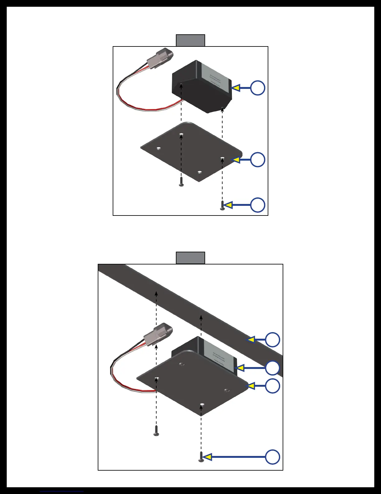
Fig. 22
A
B
C
7. Attach the replacement rear sensor (Fig. 22A) to the mounting plate (Fig. 22B) using two
⁄
" hex
head self-tapping screws (Fig. 22C). Orientation is imperative for the correct operation of the leveling
system.
8. Attach the mounting plate (Fig. 23C) and replacement sensor (Fig. 23B) assembly to the crossmember
(Fig. 23A) using two
⁄
" hex head self tapping screws (Fig. 23D). Ensure that the plate is centered side
to side on the frame and that the sensor is oriented properly (Fig. 23).
Fig. 23
A
B
C
D

Other manuals for Lippert Components ground control 3.0

Questions and Answers:

Question and Answer IconNeed help?

Do you have a question about the Lippert Components ground control 3.0 and is the answer not in the manual?

Lippert Components ground control 3.0 Specifications

General IconGeneral
BrandLippert Components
Modelground control 3.0
CategoryLifting Systems
LanguageEnglish

Related product manuals