5
Ground Control® 3.0
Aftermarket Manual
lci1.com (574) 537-8900 Rev: 04.19.18
CCD-0001307
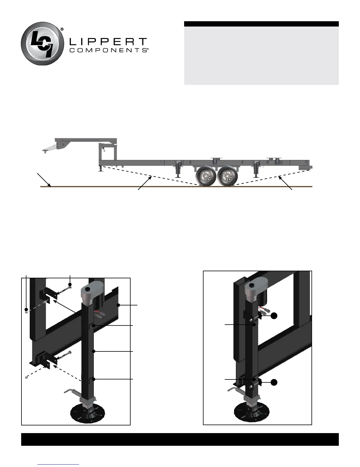
Landing Gear
1. Remove existing landing gear (front jacks) from the trailer by
removing the carriage bolts and nuts in the brackets holding
the front jacks in place.
2. Using the new carriage bolts and nuts, mount the new front
jacks in the brackets so that the tabs on the new front jacks
are positioned between the mounting brackets as shown
Main Frame
Rail
Tab
Landing Gear
Tab
Carriage BoltNut
A
Tab
Tab
A
Fig.6 Fig.7
Fig.5
Measuring Departure and Approach Angle
To measure departure and approach angles, run a string line from the meeting point of the tire and the ground up at an angle to the
lowest point on the front or rear of the trailer. These string lines are shown as dotted lines (Fig. 5).
Ground
Approach Angle String Line Departure Angle String Line
Installation
(Fig. 6 and Fig. 7). Tighten the nuts on the carriage bolts until
the bracket opening is less than 2 1/2 ” (Fig. 7A).
3. Connect the wire harnesses to the front jack motor wires and
run the harnesses to the compartment where the controller
will be mounted.
Note: LCI recommends zip-tying the harnesses tight against the
front jack motors to prevent damage to the harnesses.
 Loading...