7
Ground Control® 3.0
Aftermarket Manual
lci1.com (574) 537-8900 Rev: 04.19.18
CCD-0001307
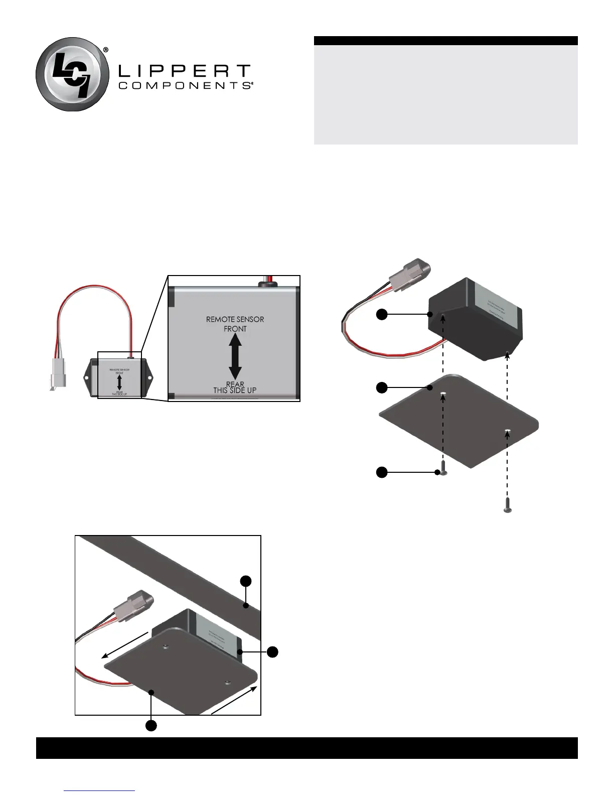
Rear Sensor
Note: The rear sensor (Fig. 10) MUST be installed on a
crossmember in line with or behind the rear jacks, centered
curbside to roadside on the trailer with the arrows on the top
of the sensor pointing the correct direction (Fig. 10 Detail).
1. Dry t the mounting plate (Fig. 11A) and the rear sensor (Fig.
11B) to the crossmember (Fig. 11C). The pre-drilled holes in
the plate are for mounting the rear sensor to the plate. Mark
on the plate where the rear sensor will set. Space between
the sensor and the crossmember MUST be left so the wire
harness will not be pinched.
Fig. 10 Detail
2. Attach the rear sensor (Fig. 12B) to the mounting plate
(Fig. 12C) using two #8 - 18 x 1” self-drilling screws (Fig.
12A). Orientation is imperative for the correct operation of the
leveling system.
A
B
C
A
B
C
Front
Rear
Fig.10
Fig.11
Fig.12
 Loading...