4
Level-Up®
Aftermarket Manual
www.lippertcomponents.com (574) 537-8900 Rev: 09.15 - Level-Up® Aftermarket Manual
Installation
Rear Jacks
1. When fully retracted, the rear jacks MUST be mounted to
achieve a minimum ground clearance equal to the departure
angle (Fig. 1) to enable maximum level correction. Any
additional ground clearance added to the jack location will
decrease the amount of level correction available to the
system.
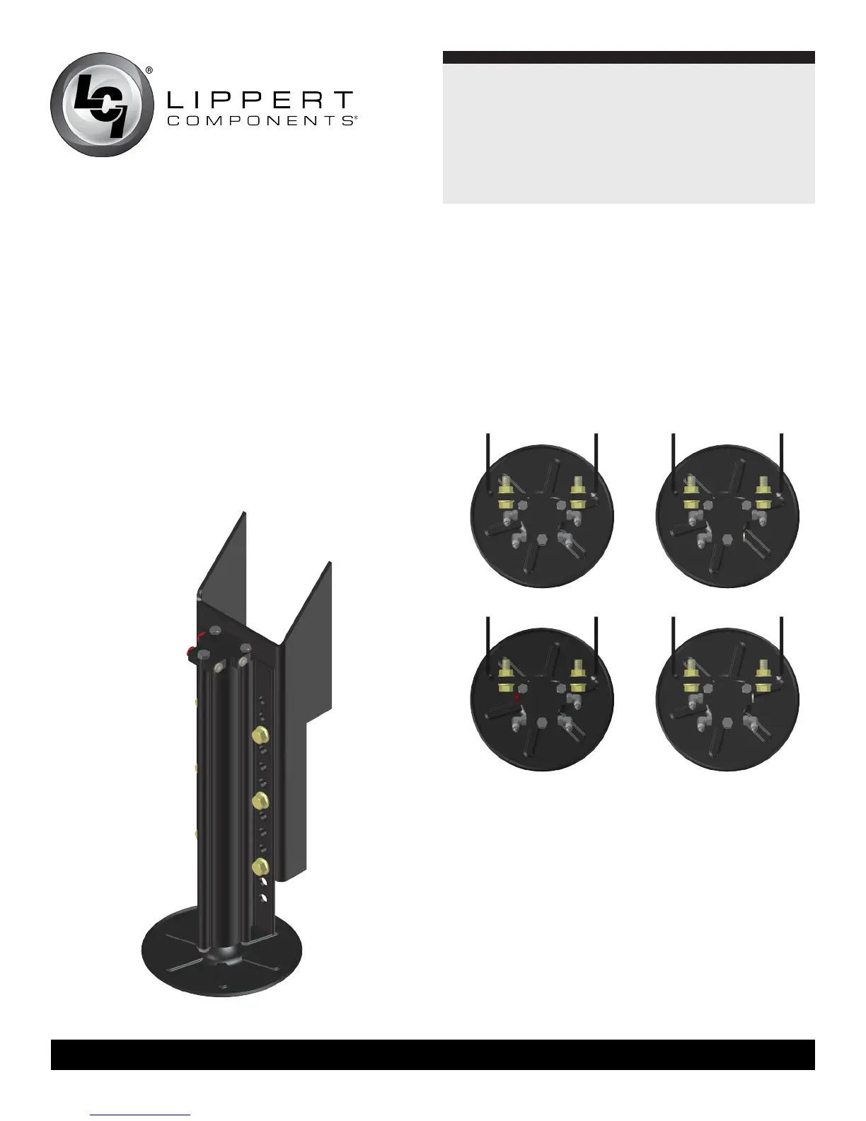
2. Bolt the leveling jacks to the mounting brackets to achieve
proper ground clearance. Make sure the bolts are tightened to
the proper torque (52-64 ft/lbs). (Fig.3).
4. Identify power unit mounting location. This will determine the
orientationofthehydraulicttings.Ifthepowerunitis,orwill
be, mounted on the driver’s side of the front compartment,
thedriver’ssidefrontlevelingjackwillbetherstjackinthe
system.
5.Installhydraulicttingstolevelingjacks.See(Figs.4-7)for
detailsofttingplacement.
6.Ifnomodicationstothejackbracketsarenecessary,skipto
Step 9.
NOTE:Drytthejackbracketstothechassisofthecoachframe.
The rear jacks must be mounted within the departure angle,
should be aligned with each other from side to side, and
mounted 12”-18” behind the rear axle on a tandem axle coach
and right at the wheel on a tri-axle coach. The front jacks can
be offset from each other side to side by up to 24” in order to
tthejacksaroundstepsorotherobstructions.Theuniversal
mountingbracketsaredesignedtota12”I-Beamwithno
modications.However,theframeonthecoachmaynotbe
12” or there may be obstructions where the jacks are to be
mounted.Ifthatisthecase,measureforthemodicationsyou
need to make to the jack brackets.
Fig.3
Fig.4 Fig.5
Fig.6 Fig.7
 Loading...