6
Level-Up®
Aftermarket Manual
www.lippertcomponents.com (574) 537-8900 Rev: 09.15 - Level-Up® Aftermarket Manual
16.Secureallhosestotheproperttingsoneachjack.Orange
hosesconnecttothettingsclosesttotheframe.Blackhoses
connecttothettingsfarthestawayfromtheframe.SeeLIP
Sheet 0215 for correct hose connection ports. See also the
plumbing diagram for a color coded illustration of the hose
orientation.
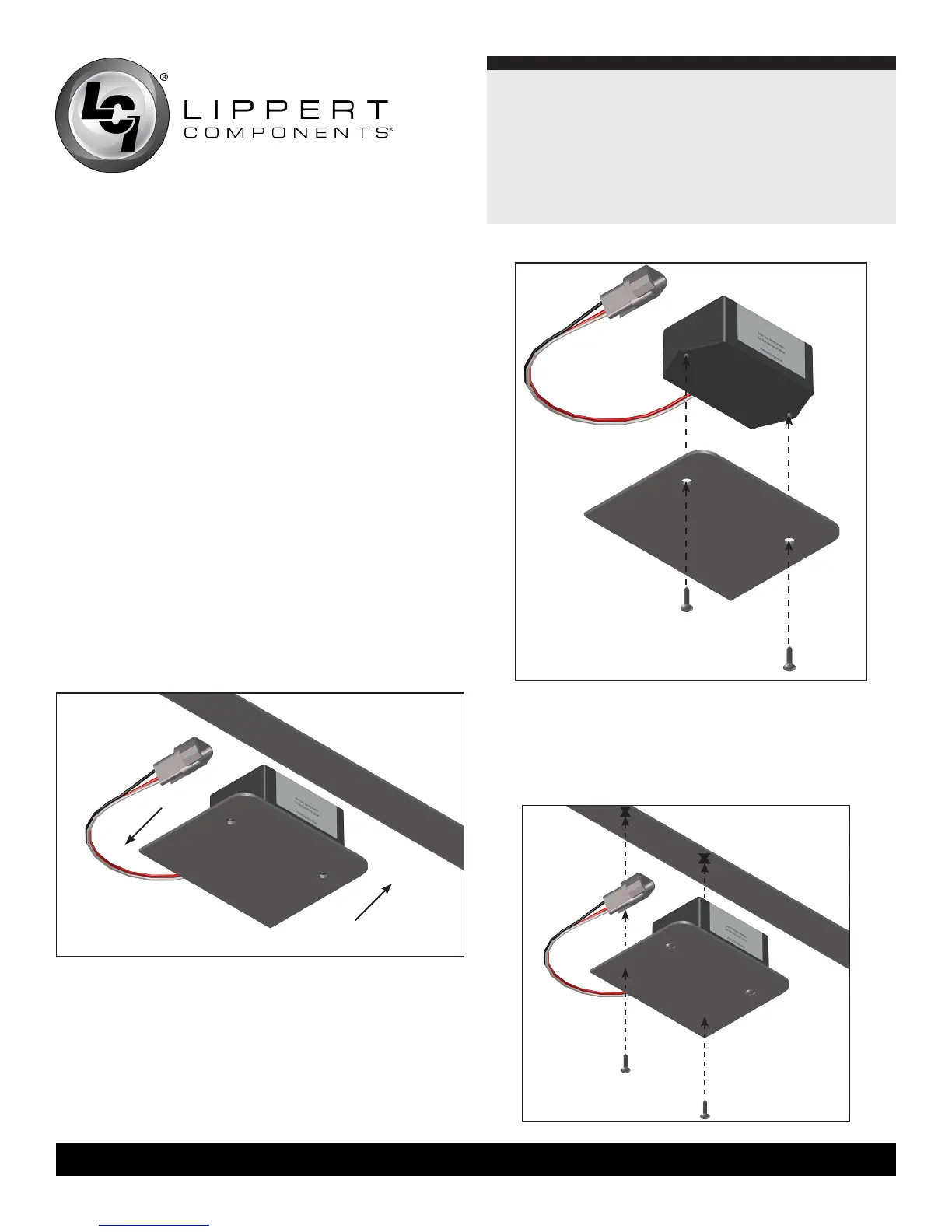
Rear Sensor
The rear sensor must be installed on the crossmember to the
rear of the back axle, centered from curbside to roadside
on the unit with the arrows on the top of the sensor
pointing the correct direction. Orientation is imperative for
the correct operation of the leveling system (Fig. 12).
1. Dry fit the mounting plate and the rear sensor to the
crossmember. The pre-drilled holes in the plate are for
mounting the rear sensor to the plate. Space between
the sensor and the crossmember must be left so the wire
harness will not be pinched.
3. Attach the mounting plate and rear sensor assembly to the
crossmember using two 3/8" hex head self tapping screws.
Ensure that the plate is centered side to side on the frame and
that the sensor is oriented properly (Fig.14).
x
2. Attach the rear sensor to the mounting plate using two #8 x
1” self tapping screws (Fig. 13).
x
Front
Rear
Fig.12
Fig.13
Fig.14
 Loading...