Solar charge controller MPPT-DC series User Manual
10.Safety Features
Short circuit
Over current
Over voltage
Over temp.
Reverse
polarity
Solar terminal
Protected *2
Protected*1
Protected
Max *3
Battery terminal
Protected
Protected *2
Max*4
Load terminal
Protected
Switches off
Switches off
with delay
The controller cuts off the load if the
temperature reaches the set value.
Switches off
immediately
Reverse
Current
Under
voltage
*1.
damaged if short-circuit just happened in the PV array.
Warning: It is forbidden to short-circuit the PV array during
charging .Otherwise, the controller may be damaged.
*2.Battery must be protected by fuse, otherwise battery will be
damaged.
*3.Please refer to "12.Technical Data" to get the max voltage
of PV panel.
*4.Please refer to "12.Technical Data" to get the max voltage
of battery.
When the PV doesn't charge, the controller will not be
!
conditions may cause damage to the controller.
Always remove the error before you continue connecting
the controller.
Warning: The combination of different error
9.2Faults & Alarms
Fault
Status
Reason Remedy
Over
voltage
protection
Batt ery
can’ t be
char ged
Overcurrent,
short circuit
protection
Battery capacity
is low
Loads are
over current
or short circuit
High battery
voltage
>15.5V/31.0V
PV panel fault
or reverse
connection
Load will be reconnected
when battery is recharged
Switch off all loads,
remove short circuit,
load will be reconnected
after 1 minute automatically
All LED
fast flashing
Battery voltage
is not in right
range
Charge or discharge,
make battery voltage
in the right range
Gree n
LED
is on
Low
voltage
protecti on
Low volt.
prote ctio n
Over temp.
protection
Controller temp.
is too high
Load reconnects
after temp. reduces
High
voltage
at
battery
terminal
Can’t
recognize
system
voltage
Loads
are
not
powered
Check if other sources
overcharge the battery.
If not,controller is damaged.
Battery wires or
battery fuse
damaged,
battery has high
resistance.
Check battery wires,
fuse and battery.
Battery is
empty
after a
short time
Battery has low
capacity
Change battery
Check panels and
connection wires
*
Gel, Liquid and AGM: Battery overvoltage >15.5/31.0V
Lithium: Battery overvoltage >(CVT+0.2V)
Page 5 of 7 pages
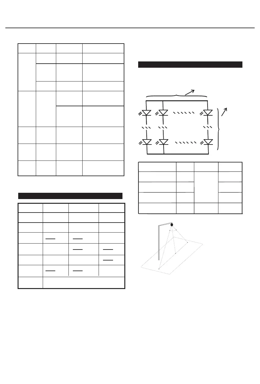
11.Recommended connection of LED lights
Following connect ways is for the LED lights
(Vf: 2.9V~3.4V; I: 300mA, Power: 1W )
n for number of parallel connection
m for number of
in series connection,
MPPT1050-DCLi
MPPT0850
-DCLi
MPPT0875-DCLi
MPPT1575/2075
-DCLi
Infrared sensor
θ(Angle):60°
H(Height):7m
D(Width):8m
Microwave sensor
θ(Angle):150°
H(Height):15m
D(Width):7m
Θ
H
D
!
lampshade will reduce the sensitivity.
2) Sensor range will change with temperature, light
conditions and so on, subject to the actual measurement.
3) The distance between any inductive sensors should be
greater than 3m.
4) Please ensure that there are no moving signals around
the sensor, such as fan, DC motor, sewer pipe, air outlet,
etc., the sensor may generate false trigger.
1) The sensor which installed in the plastic and glass
11.2 Sensor
11.1 Load
LED chips
connection
Load
current
Output
Voltage
System
Voltage
M=7~18
N=1~20
20~55V
0.15~6.0A
M=7~14
N=1~10
M=7~10
N=1~10
M=7~18
N=1~10
20~45V
20~35V
20~58V
0.15~3.0A
 Loading...