31
should be made timely. During adjustment, firstly support the front wheels off the ground,
and dismantle the bearing cover and pull out the split cotter on nut (6), then screw nut (6)
until the bearing clearance is eliminated, and return the nut (6) in 1/15-1/7 turn, then lock the
nut with split cotter, and assemble the bearing cover.
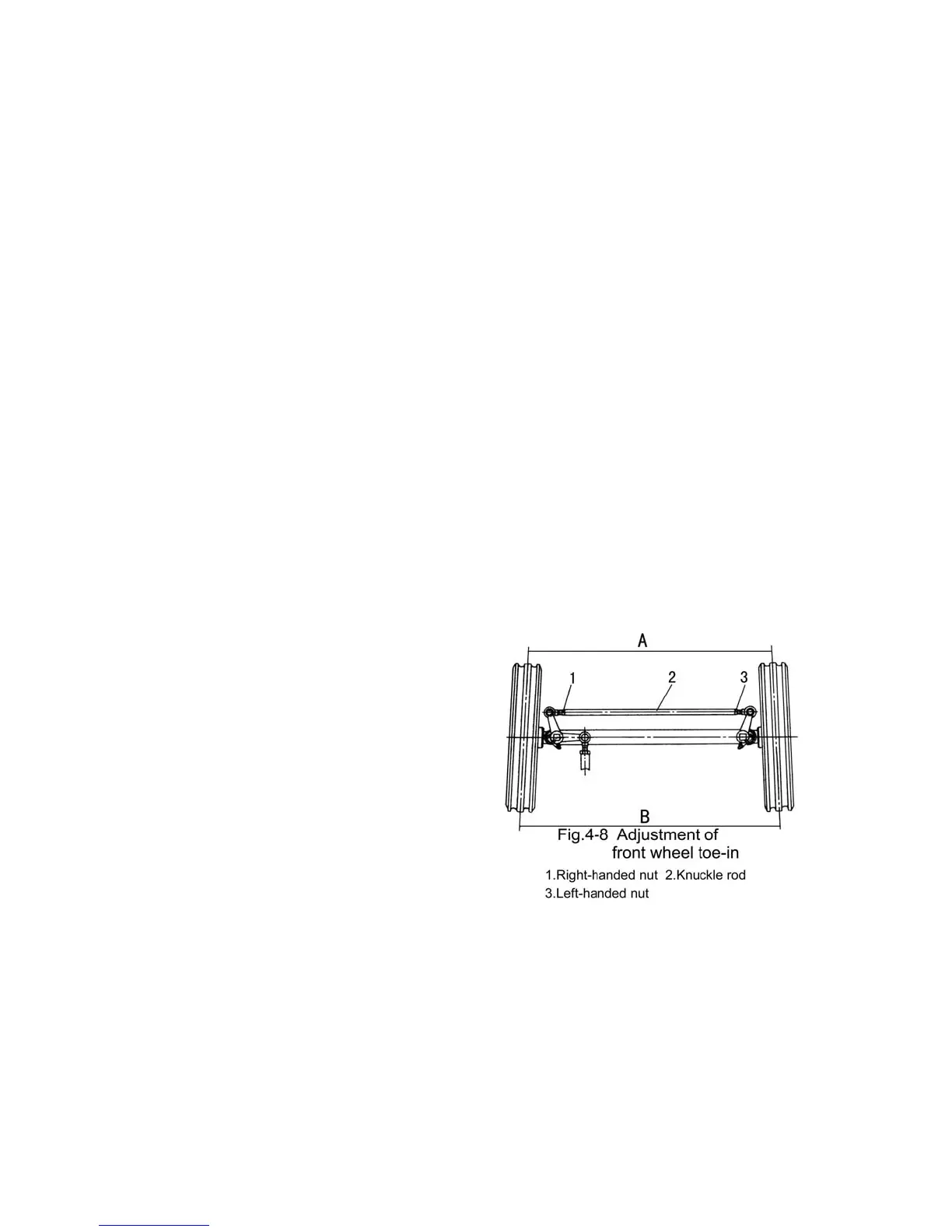
2) Adjustment of front wheel toe-in
During the operation of the tractor, the front wheel toe-in will change due to
deformation and wear out of the parts of steering mechanism and front axle. If the toe-in is
not adjusted in time, the wear of the front wheel will accelerate. The adjustment steps of toe-
in are as follows:
a. Stop the tractor on level ground, place the front wheels on rectilinear walking
position.
b. Measure the distance A and B between the two wheels (Distance A is the distance
between the forefront of the two wheels. B is the distance between the rearmost ends of the
two wheels.) at the same horizontal plane through the centers of the two wheels circumference.
c. Loosen the locking nuts (1) and (3) on both sides of the knuckle rod (2); turn the
knuckle rod to make B-A=4-10mm, then retighten knuckle rod (2) with nuts (1) and (3).
6. Adjustment of front drive axle
1) Adjustment of main drive (Fig.4-9)
During assembling, choose the suitable
bearing seat gasket (9) of driving bevel gear
and adjust the adjusting nuts (3) on the both
sides to make the mesh backlash of the gear
pairs of the main drive be 0.15-0.30mm, and
ensure the contacting area, i.e. the meshing
contact traces of the gear pairs should be
adjusted to the middle of gear tooth faces and slightly nearer to the small end; and should
also ensure that no axial movement of the bearings on either end will appear, and that the
differential assembly could turn freely. Adjust the position of the concave slot of the nut to
make the locating plate of the cover be inserted smoothly, then lock the nut.
 Loading...


