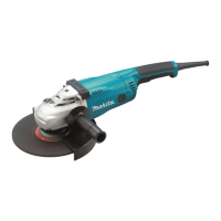
Circuit diagram
Wiring diagram
P 9/ 9
Fig. D-1
Power supply cord
Switch
Noise
suppressor
Controller
Makita
logo side
Brown lead wire is used
for some countries.
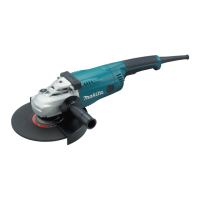
Fig. D-2
Blue lead wire is used for some countries.
Blue lead wire is used
for some countries.
Makita
logo side
Pass Field lead wires (black, white)
by this Hook.
Guide out Field lead wire
(white) by this Hook.
Guide out Field lead wire
(black) by this Hook.
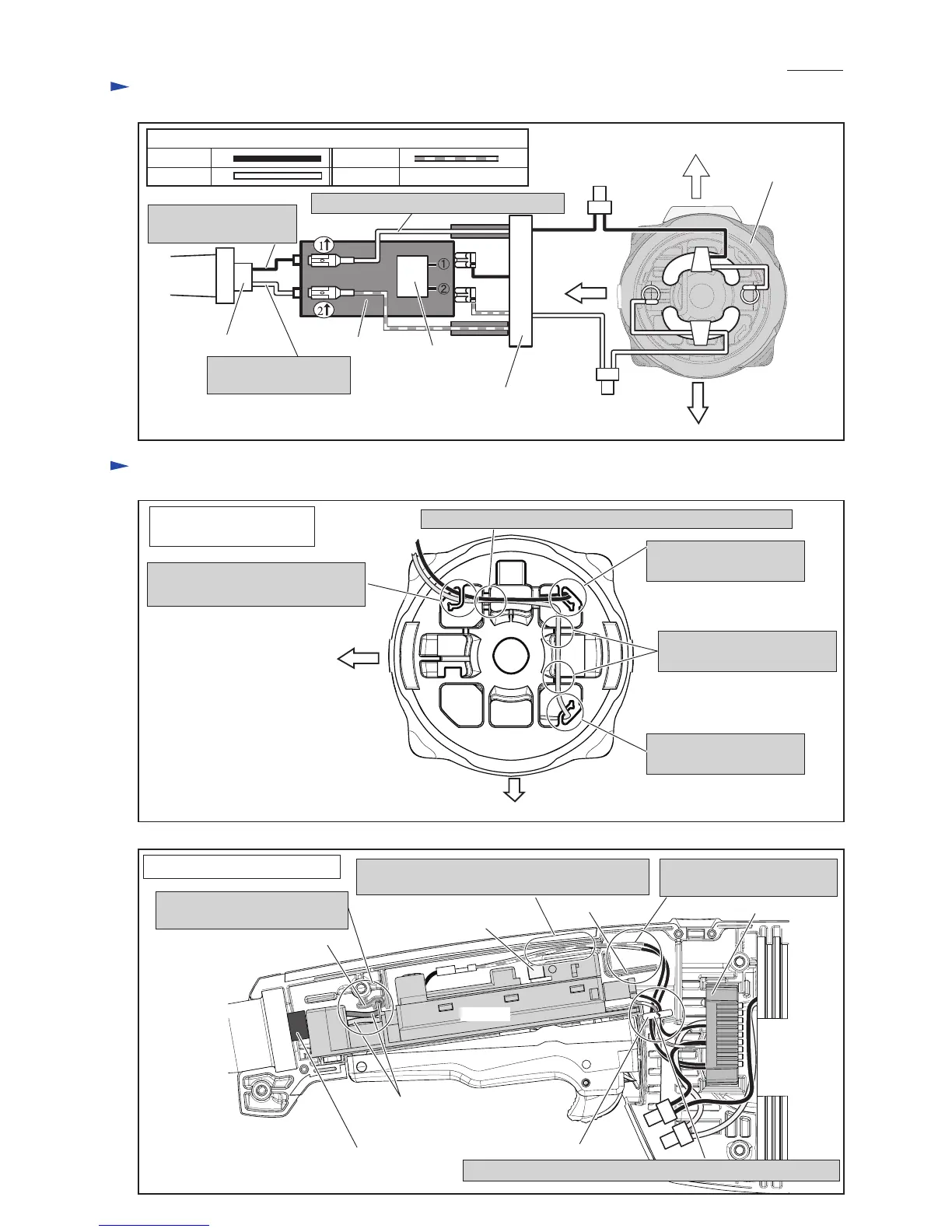
Belly side
(Name plate side)
Belly side (Name plate side)
Back side
(Bumper side)
White
Color index of lead wires' sheath
Black Red
Motor housing
viewed from
Commutator side
Fix Field lead wire (white)
with these Lead wire holders.
Fix Field lead wires (black, white) with this Lead wire holder.
Wiring in Motor housing
on Commutator side
Fig. D-3
Noise suppressor
Power supply cord
Lead wires of
Power supply cord
Put Lead wires of power supply
cord between Switch and Rib.
Controller
Switch
Rib
Rib
Sponge sheet
Pass Controller’s Lead wires (black, red) through Sponge sheet.
Pass Controller’s Lead wires
(white, red) by the Rib.
Do not pinch Controller’s lead wires (white, red)
between Switch and inner wall of Handle set.
Wiring in Handle complete (L)

 Loading...