EasyManuals Logo

Makita HR2470 Technical Information

Makita HR2470
20 pages
To Next Page IconTo Next Page
To Previous Page IconTo Previous Page
Page #19 background imageLoading...
Page #19 background image
Repair
[4] Maintenance Program
When replacing carbon brush, it is recommended to replace
the parts listed in the table below at the same time
for longer service life of the machine. (Fig. 69)
Fig. 69
Steel ball 7 O ring 9
O ring 16
P 19 / 20
Circuit diagram
Color index of lead wires' sheath
Black
White
Blue
Brown
Brush holder
Switch
Noise suppressor
built in Switch
For some countries,
black colored lead
wire is used instead of
brown.
For some countries,
white colored lead
wire is used instead of
blue.
Brush holder unit
Power supply cord
For some countries,
Noise suppressor is not
built in Switch.
Light
circuit
Light circuit is built
in HR2470F and HTR2470FT.
Fig. D-1

Other manuals for Makita HR2470

Questions and Answers:

Question and Answer IconNeed help?

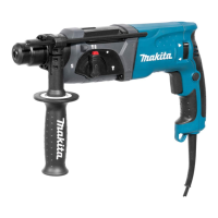
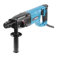
Do you have a question about the Makita HR2470 and is the answer not in the manual?

Makita HR2470 Specifications

General IconGeneral
Input power780 W
Power sourceAC
Impact rate4500 bpm
Impact energy (max)2.4 J
Drilling diameter in wood (max)32 mm
Drilling diameter in steel (max)13 mm
Drilling diameter in concrete (max)24 mm
ReverseYes

Related product manuals