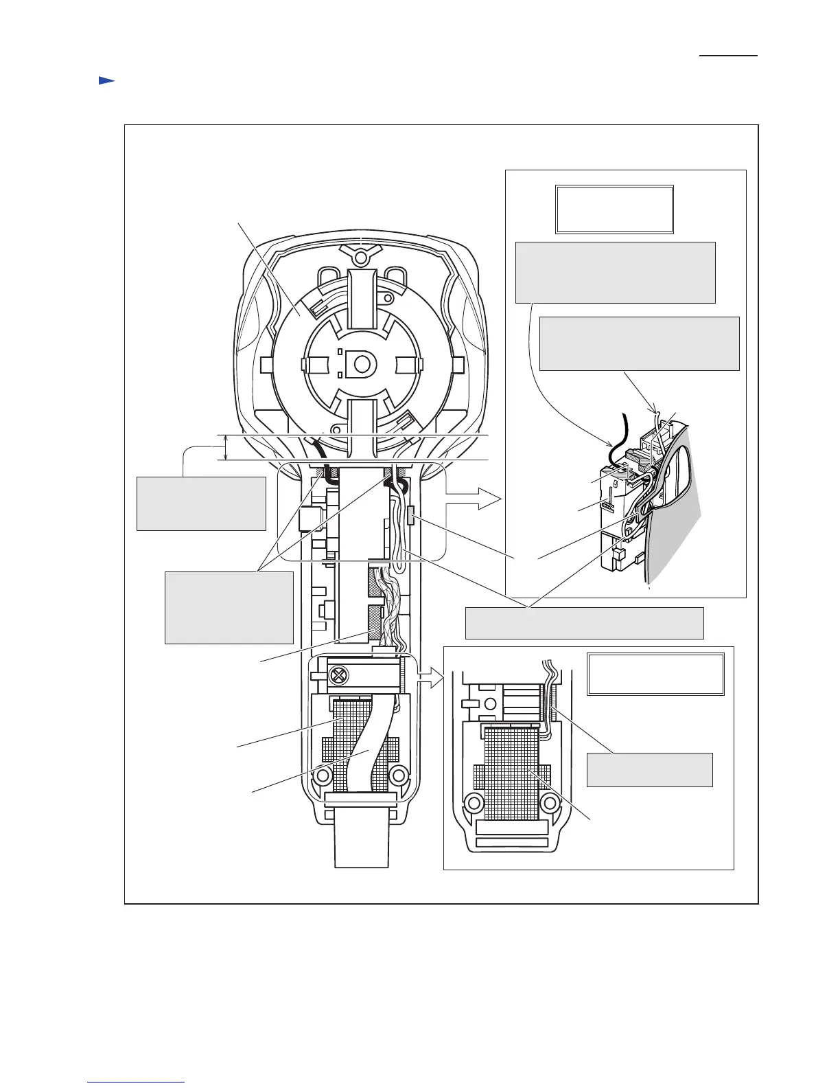
Wiring diagram
P 20 / 20
Noise suppressor
built in Switch
(Noise suppressor is not
used for some countries.)
Light circuit
(only for HR2470F and
HR2470FT)
Brush holder unit
Switch
Light circuit
(only for HR2470F and
HR2470FT)
Wiring under
Power supply cord
Put Lead wire of Light
circuit into the groove.
Power supply cord
Fix the Brush holder
lead wires (black and
white) with these lead
wire holders.
Rib
Route Brush holder lead wire (black)
between projections of Terminal M1
and M2, and connect it to Switch
terminal M2.
Route Brush holder lead wire (white)
between Switch and Grip,
and connect it to Switch terminal M1.
Brush holder lead wires
(black and white) must be
tight in this portion.
Put the slack of Brush holder lead wire (white)
in this position.
Wiring of Brush holder
lead wires
(black and white)
Terminal M2
Terminal M1
Switch
Grip portion
Fig. D-2

 Loading...