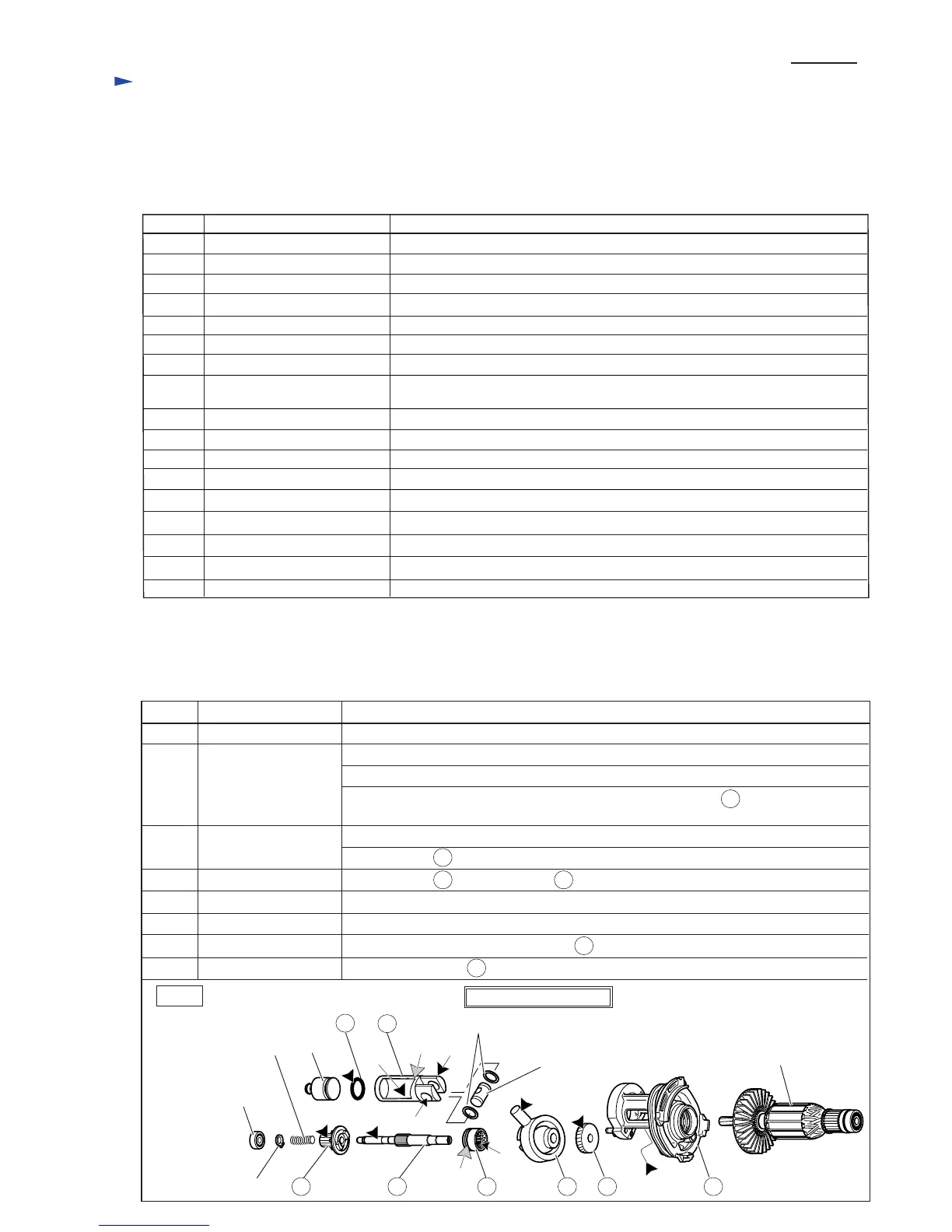
[2] LUBRICATION
[1] NECESSARY REPAIRING TOOLS
CAUTION: Remove the Bit from the machine for safety before repair/ maintenance in accordance with
the instruction manual!
Note: Regarding the repair for 2 mode Rotary hammers, refer to the data as follows;
HR2230-TE.pdf, HR2460-TE.pdf, HR2460F-TE.pdf
Fig. 1
Repair for 3 mode Rotary Hammers HR2470, HR2470F, HR2470T and HR2470FT
Item No. Description Portion to lubricate
DescriptionCode No. Use for
Retaining ring S pliers ST-2N
1R003 Removing Ring spring 19
Retaining ring S pliers ST-2
1R004 Removing Ring spring 21 and Ring spring 29
Bearing plate(for arbor press)1R022 Attachment of 1R306 / Removing Ring 8 and Helical gear 26
Removing Ring 8 and Helical gear 26
Pipe ring (for arbor press)1R023
Bearing setting plate 8.21R032 Assembling Swash bearing 10
Assembling Helical gear 26Bearing setting plate 10.21R033
Armature holder 32 set for use
with vise
1R038
Holding Tool holder when removing Ring spring 28 from Tool holder
Ring spring setting tool A1R164 Assembling Oil seal 25 and Needle bearing complete to Gear housing complete
Ring spring setting tool B1R165 Assembling Needle bearing complete into Gear housing complete
Tip for Retaining ring pliers1R212 Attachment of 1R003
Pipe 301R232 Assembling Oil seal 25 to Gear housing complete
Round bar for arbor 30-1001R252 Removing Oil seal 25 from Gear housing complete
Bearing extractor1R269 Removing Ball bearing 608ZZ from Swash bearing section
Round bar for arbor 7-50
1R281
Removing Tool holder section, Ring 8 and Helical gear 26
1R291
Removing Retaining Ring S-7 from Cam shaft
Ring spring removing jig
1R306 Removing Ring spring 29 from Tool holder
Piston cylinder
317517-9 Assembling Ring spring 28 to Tool holder
Retaining ring S and R pliers
Striker
Ball bearing 606ZZ
Compression spring 7
Retaining ring S-7
Piston joint
Armature
Flat washer 12
Swash Bearing Section
35
36
44
46 47
56
(f)
(g)
(h) (g)
(i)
(j)
Apply the following grease to protect parts and product from unusual abrasion.
* Makita grease R No.00 to the portions marked with black triangle
* Molybdenum disulfide lubricant to the portions marked with gray triangle
45
90
44
46
47
56
35
36
Clutch cam
Swash bearing 10
Helical gear 26
Inner housing complete
O ring 16
Piston cylinder
Whole portion
Pole portion which is inserted into Piston joint
90 Spur gear 10 Teeth portion where 23 Spur gear 51 engages
Teeth portion
Space where Armature's drive end and 47 Helical gear 26 engages
(f) Inside where Striker moves
(g) Hole for accepting Piston joint
(h) Apply Molybdenum disulfide lubricant to the surface where 25 Tool holder contacts.
(i) Apply Molybdenum disulfide lubricant to the groove.
(j) Side where 46 Swash bearing 10 engages
45 Cam shaft Surface where 44 Clutch cam and 90 Spur gear 10 contact
P 2 / 20

 Loading...