16
2
(1)
(2)
(1)
(2)
(2)
(1)
(2)
(1)
(1)
(2)
(3)
(4)
1
001557
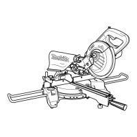
Measuring
Measure the wall length and adjust workpiece on
table to cut wall contact edge to desired length.
Always make sure that cut workpiece length at the
back of the workpiece is the same as wall length.
Adjust cut length for angle of cut. Always use
several pieces for test cuts to check the saw
angles.
When cutting crown and cove moldings, set the
bevel angle and miter angle as indicated in the
table (A) and position the moldings on the top
surface of the saw base as indicated in the table
(B).
In the case of left bevel cut
Molding
position in
Fig. A
Bevel angleMiter angle
For outside
corner
For inside
corner
52/38° type 45° type
Right 31.6°
45° type
Left 33.9° Left 30°
52/38° type
Left 31.6° Left 35.3°
Right 35.3°
Right 35.3°Right 31.6°
(1)
(2)
(3)
(4)
Table (A)
006361
Molding
position in
Fig. A
Molding edge against
guide fence
(1)
Ceiling contact edge should
be against guide fence.
Ceiling contact edge should
be against guide fence
.
For
outside
corner
Finished piece
will be on the
Left side of
blade.
Finished piece
will be on the
Right side of
blade.
For inside
corner
Wall contact edge should be
against guide fence
.
Finished piece
(2)
(3)
(4)
Table (B)
006362
Example:
In the case of cutting 52/38° type crown
molding for position (1) in Fig. A:
• Tilt and secure bevel angle setting to
33.9° LEFT.
• Adjust and secure miter angle setting to
31.6° RIGHT.
• Lay crown molding with its broad back
(hidden) surface down on the turn base
with its CEILING CONTACT EDGE
against the guide fence on the saw.
• The finished piece to be used will
always be on the LEFT side of the
blade after the cut has been made.
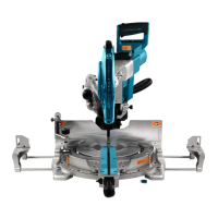
7. Cutting aluminum extrusion
1
2
3
4
5
010404
When securing aluminum extrusions, use spacer
blocks or pieces of scrap as shown in the figure to
prevent deformation of the aluminum. Use a
cutting lubricant when cutting the aluminum
extrusion to prevent build-up of the aluminum
material on the blade.
WARNING:
• Never attempt to cut thick or round aluminum
extrusions. Thick or round aluminum extrusions
can be difficult to secure and may work loose
during the cutting operation which may result in
loss of control and serious personal injury.
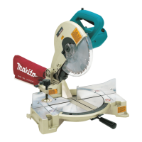
8. Wood facing
Use of wood facing helps to assure splinter-free
cuts in workpieces. Attach a wood facing to the
guide fence using the holes in the guide fence.
See the figure concerning the dimensions for a
suggested wood facing.
15mm Over 450 mm
62mm-65mm
18 mm
45mm
103mm 65mm 103mm
1
1
014279
CAUTION:
• Use straight wood of even thickness as the wood
facing.
WARNING:
• Use screws to attach the wood facing to the
guide fence. The screws should be installed
so that the screw heads are below the surface
of the wood facing so that they will not
1. Holes
1. Guide fence
2. Vise
3. Spacer block
4. Aluminum
extrusion
5. Spacer block
1. Inside corner
2. Outside corner
 Loading...