10 ENGLISH
Removing or installing cut-o wheel
CAUTION: Be sure to tighten the hex socket
bolt securely.Insucienttighteningmayresultin
severeinjury.Whentighteningthehexsocketbolt,
use the hex wrench provided with the tool to assure
proper tightening.
CAUTION: Always use only the proper inner
and outer anges which are provided with the
tool.
CAUTION: Always lower the safety guard
after replacing the wheel.
CAUTION: Wear gloves when handling
wheels.
►Fig.9: 1.Innerange2. Ring 3. O-ring 4. Bonded
reinforcedcut-owheel5.Outerange
6. Washer 7.Hexsocketbolt
Raisethesafetyguard.Turnthehexsocketboltcoun-
terclockwise using a hex wrench while holding down the
shaftlock.Thenremovethehexsocketbolt,washer,
outerangeandwheel.
►Fig.10: 1. Shaft lock 2.Hexsocketbolt
To install the wheel, follow the removal procedures in
reverse.Makesuretottheholeofcut-owheeltothe
ring and return the safety guard.
Hex wrench storage
►Fig.11: 1. Hex wrench
When not in use, store the hex wrench as shown in the
guretokeepitfrombeinglost.
OPERATION
CAUTION: Proper handle pressure during
cutting and maximum cutting eciency can
be determined by the amount of sparks that is
produced while cutting. Do not force the cut
by applying excessive pressure on the handle.
Reducedcuttingeciency,prematurewheelwear,as
wellas,possibledamagetothetool,cut-owheelor
workpiece may result.
Holdthehandlermly.Switchonthetoolandwaituntil
thecut-owheelattainsfullspeedbeforelowering
gentlyintothecut.Whenthecut-owheelcontacts
theworkpiece,graduallybeardownonthehandleto
performthecut.Whenthecutiscompleted,switcho
the tool and wait until the cut-o wheel has come to
a complete stop beforereturningthehandletothefully
elevated position.
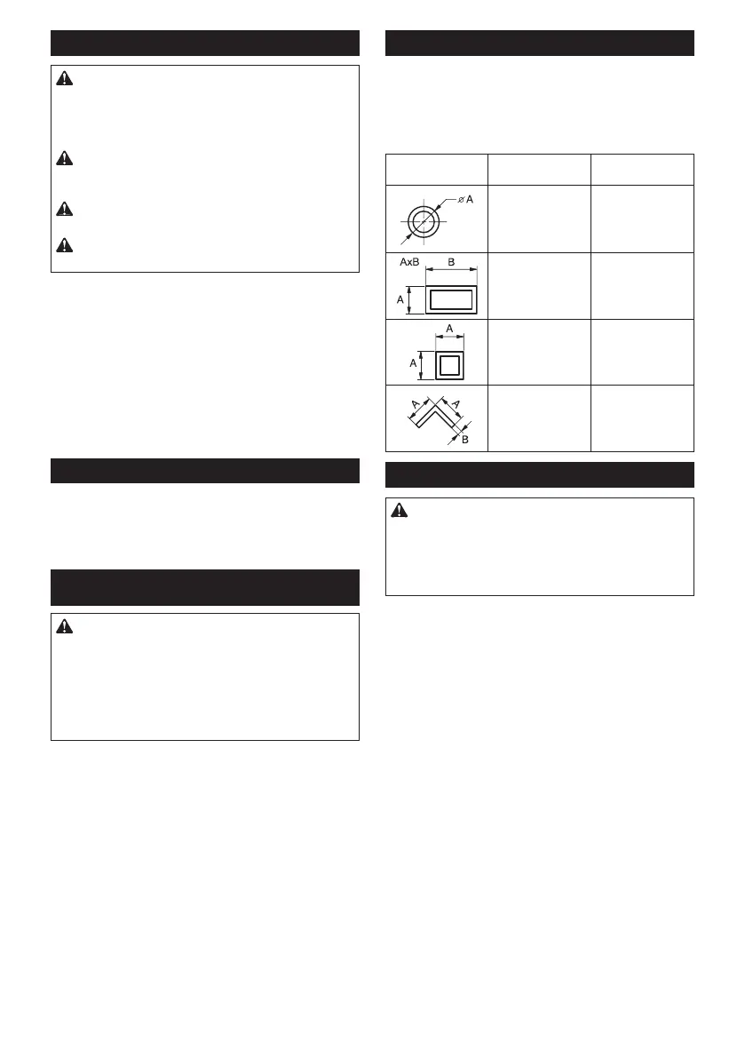
Cutting capacity
Maximum cutting capacity varies depending on the
cutting angle and workpiece shape.
Max. cutting capacity with a brand-new cut-o
wheel
Cutting angle /
Workpiece shape
90° 45°
127 mm
(5")
127 mm
(5")
102 x 194 mm
(4" x 7-5/8")
70 x 233 mm
(2-3/4" x 9-1/8")
115 x 103 mm
(4-1/2" x 4-1/16")
119 x 119 mm
(4-11/16" x
4-11/16")
106 x 106 mm
(4-3/16" x 4-3/16")
137 x 137 x 10 mm
(5-3/8" x 5-3/8"
x 3/8")
100 x 100 x 10 mm
(4" x 4" x 3/8")
Securing workpiece
CAUTION: Always place the thread holder on
the shaft threads when securing the workpiece.
Failuretodosomayresultininsucientsecuringof
theworkpiece.Thiscouldcausetheworkpiecetobe
ejectedorcauseadangerousbreakageofthecut-o
wheel.
Whilethethreadholderislifted,theviseplatecanbe
moved in and out quickly. To grip a workpiece, push the
handle until the vise plate contacts the workpiece then
return the thread holder. Turn the handle clockwise until
the workpiece is securely retained.
►Fig.12: 1. Handle 2. Thread holder 3. Vise plate
Whenthecut-owheelhasworndownconsiderably,
placeaspacerblockbehindtheworkpieceasshown
inthegure.Youcanmoreecientlyutilizetheworn
wheelbyusingthemidpointontheperipheryofthe
wheeltocuttheworkpiece.Useasturdyandnon-am-
mablematerialforaspacerblock.
►Fig.13: 1.Spacerblock
When cutting workpieces over 85 mm (3-3/8") wide at
an angle, attach a straight piece of wood (spacer) over
190 mm (7-1/2") long x 45 mm (1-3/4") wide to the guide
plateasshowninthegure.Attachthisspacerwith
screws through the holes in the guide plate. Make sure
thatthecut-owheeldoesnotcontactthespacerwhen
the tool head is depressed.
►Fig.14: 1. Guide plate 2.Spacerblockover
190 mm (7-1/2") long x 45 mm (1-3/4") wide
3. Workpiece over 85 mm (3-3/8") wide
4. Vise plate
►Fig.15
 Loading...