16 ENGLISH
Reverse button for debris removal
WARNING: Switch o the tool and remove
the battery cartridge before you remove entan-
gled weeds or debris which the reverse rotation
function can not remove.Failuretoswitchoand
remove the battery cartridge may result in serious
personalinjuryfromaccidentalstart-up.
This tool has a reverse button to change the direction of rotation.
It is only for removing weeds and debris entangled in the tool.
To reverse the rotation, tap the reverse button and pull the
switchtriggerwhiledepressingthelock-oleverwhenthe
cutting tool is stopped. The speed indicators and ADT indi-
cator start blinking, and the cutting tool rotates in reverse
direction when you pull the switch trigger.
To return to regular rotation, release the trigger and wait
until the cutting tool stops.
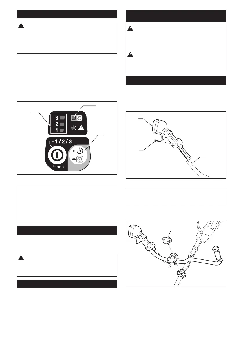
3
2
1
►
1. Speed indicator 2. ADT indicator 3. Reverse button
NOTE:
During the reverse rotation, the tool operates only
for a short period of time and then automatically stops.
NOTE: Once the tool is stopped, the rotation returns
to regular direction when you start the tool again.
NOTE: If you tap the reverse button while the cutting
tool is still rotating, the tool comes to stop and to be
ready for reverse rotation.
Electric brake
This tool is equipped with an electric brake. If the tool
consistently fails to quickly stop after the switch trigger
is released, have the tool serviced at our service center.
CAUTION: This brake system is not a substi-
tute for the protector. Never use the tool without
the protector. An unguarded cutting tool may result
inseriouspersonalinjury.
Electronic function
Constant speed control
The speed control function provides the constant rota-
tion speed regardless of load conditions.
Soft start feature
Soft start because of suppressed starting shock.
ASSEMBLY
WARNING: Always be sure that the tool is
switched o and battery cartridge is removed
before carrying out any work on the tool. Failure to
switchoandremovethebatterycartridgemayresult
inseriouspersonalinjuryfromaccidentalstart-up.
WARNING: Never start the tool unless it is
completely assembled. Operation of the tool in a
partially assembled state may result in serious per-
sonalinjuryfromaccidentalstart-up.
Installing the handle
For UR006G
1. Insert the shaft of the handle into the grip. Align
the screw hole in the grip with the one in the shaft.
Tighten the screw securely.
1
3
2
►1. Grip 2. Screw 3. Shaft
NOTICE: Note the direction of the grip. The
screw holes will not be aligned if the grip is not
inserted in the correct direction.
2. Adjustthehandleposition,andthentightenthe
knobtoxthehandle.
1
►1. Knob
 Loading...