Throttle lever control system
67
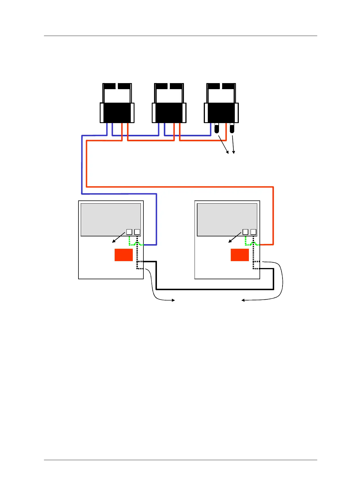
Example of CAN bus wiring on 2 engines and 3 control stands
Station1
BBStB
X21
X22
X11
X12
BBStB
X21
X22
X11
X12
Crosscommunication
BBStB
X21
X22
X11
X12
Station2
BBStB
X21
X22
X11
X12
BBStB
X21
X22
X11
X12
Station3
BBStB
X21
X22
X11
X12
Terminatingresistors
894105xxx2
S1: CAN bus throttle lever terminator
S2: Cross communication terminator
MANterminalbox
MPCBB
S1 S2
X13
X15
X14
S1−ON
S2−ON
MANterminalbox
MPCBB
S1 S2
X13
X15
X14
MANterminalbox
MPCBB
S1 S2
X13
X15
X14
S1−ON
S2−ON
MANterminalbox
MPCstdb
S1 S2
X13
X15
X14
S1−ON
S2−ON
MANterminalbox
MPCstdb
S1 S2
X13
X15
X14
MANterminalbox
MPCstdb
S1 S2
X13
X15
X14
S1−ON
S2−ON
Close off unused connections
with suitable caps
The throttle levers and MPC in the engine terminal box are connected with shielded M12 CAN bus cables.
When wiring, make sure to not cross the throttle lever CAN bus between the MPC and the throttle levers.
This can easily happen when connecting the cables.
The termination resistors must be plugged on as shown or activated via DIP switch, see page 69.
 Loading...