The following parameters can be used, for example:
▪ Analog signal for position
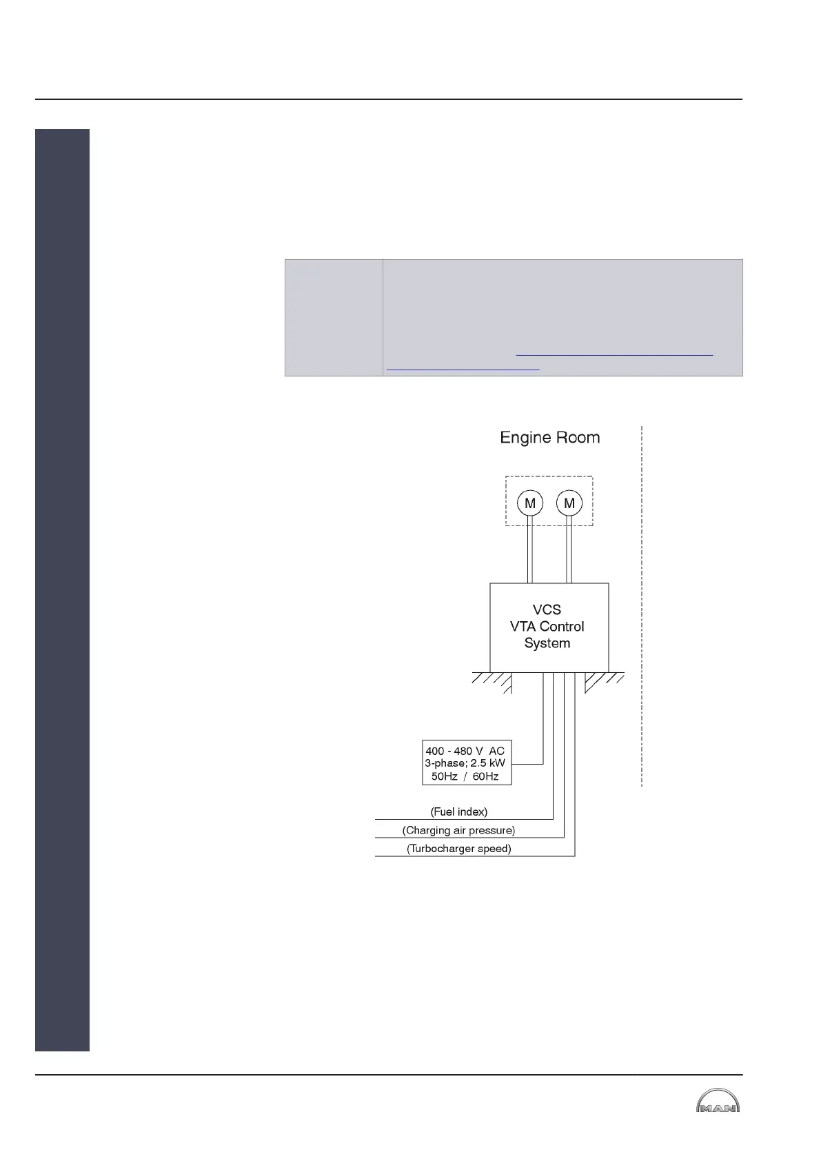
▪ Turbocharger speed
▪ Fuel index
▪ Charge air pressure
NOTE The VTA control system for the “stand-alone” variant must be
adapted, on a case-by-case basis, to the system that is to be
charged. The parameter sets for the adjustment logic are know-
how of the engine manufacturer and are loaded into the control
system via the USB interface or CD-ROM.
See schematic diagram Wiring diagram – VTA control system
(VCS) for stand-alone variant.
Figure 13: Schematic sketch – VTA control (VCS) for Stand-alone variant
4.2 Cooling Water System
The cooling water system is used for cooling the spindle drives of the adjust-
ment device.
4 Systems
4.2 Cooling Water System
2013-12-04 - de
4
MAN Diesel & Turbo
20 (38)
EN-US
 Loading...