Home
Manitowoc
Construction Equipment
18000
Manitowoc 18000 Service Maintenance Manual
4
of 1
of 1 rating
316 pages
Give review
Manual
Specs
To Next Page
To Next Page
To Previous Page
To Previous Page
Loading...
Reference
Only
Manitowoc
Published 12-05-17, Control # 035-23
4-3
18000 SERVICE/MAINTENANCE MANUAL
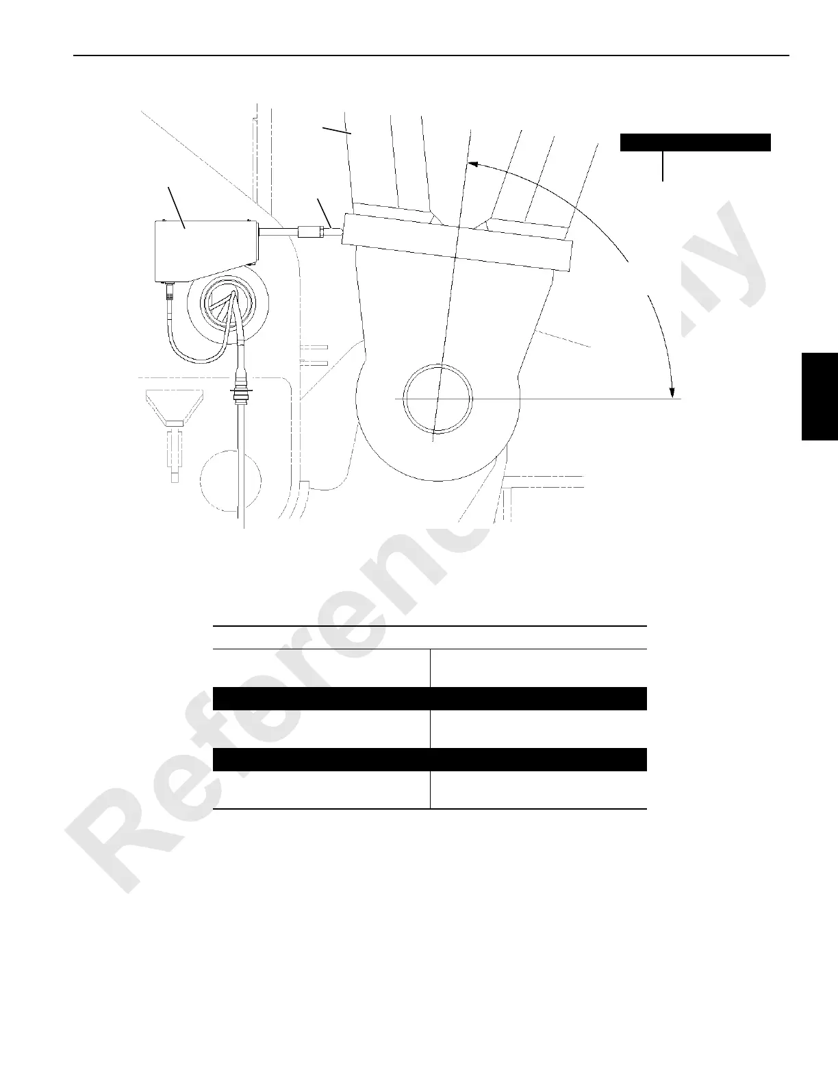
BOOM
4
1
2
Centerline of
Boom
Horizontal
A
see T
able 4-1
Item
Description
1B
o
o
m
B
u
t
t
2
Switch Assembly
Right Side of Cran
e
See T
able 4-2
2a or 2b
FIGURE 4-1
T
able 4-2 —
Adjusting Rods
Adjusting Rod Leng
th
2a
Boom Only
2b
With Luffing Jib
When Boom Up Limit
Can be Bypassed
4-3/4 in (121 mm) for 83°
4-1/2 in (1
14
mm) for 84°
3-3/4 in (83 mm)
When Boom Up Limit
Cannot be Bypassed
4-3/4 in (121 mm) for 83°
4-1/2 in (1
14
mm) for 84°
3-1/4 in (83 mm)
198
200
Table of Contents
Table of Contents
5
Section 1
13
Continuous Innovation
13
Safety Messages
13
General
13
Safety Alert Symbol
13
Signal Words
13
Safe Maintenance Practices
14
Maintenance Instructions
14
Environmental Protection
15
Identification and Location of Components
16
Basic Crane
16
Front
17
Top
18
Left Side
19
Left Side - S/N18001082 & Newer
20
Right Side
21
Rear
22
Carbody/Crawler
23
Operator Cab/Controls
24
Cummins Engine Tier 3
25
Cummins Engine Tier 4
26
Boom Butt and Insert
28
Mast Butt
29
Description of Operation
30
General Abbreviations
30
Solenoid Valve Identification
30
General Operation
31
Hydraulic Components
32
Hydraulic Tank
32
Shutoff Valves
32
Charge Filters (Past Production)
32
Suction Manifolds
32
Return Manifolds
32
Hydraulic Fluid Cooler
32
Supercharge Pumps (Past Production)
32
Charge Pressure
33
Hydraulic Motors
33
Main Pressure Monitoring
34
Accessory Systems
34
Basic Operation
35
Engine Controls
36
Drum Identification
37
Epic® Control System
38
CAN-Bus
38
Digital Display
38
Rated Capacity Indicator/Limiter (RCL)
38
Crane Modes
39
Electrical Power to Operator's Cab
39
Pressure Senders and Speed Sensors
39
System Faults
40
Engine Faults (Tier 4)
40
Operating Faults and Limit Switches
40
Brake and Drum Pawl Operation
40
Swing System Operation
42
Swing System Components
42
Swing Brake and Swing Lock
42
Swing Right or Left
42
Swing Holding Brake Switch
43
Travel System Operation
46
Travel System Components
46
Travel Brakes
46
Travel Forward and Reverse
46
Two-Speed Travel Operation
49
Travel Cruise
49
Boom Hoist System Operation
50
Boom Hoist System Components
50
Boom Hoist Brake and Pawl
50
Boom Hoist Raise
50
Boom Hoist Lower
53
Main Hoist 1 System
54
Main Hoist 1 System Components
54
Main Hoist 1 Drum Brake
54
Main Hoist 1 Raising
54
Main Hoist 1 Lowering
57
Whip Line Hoist (Drum 3) System
58
Whip Line Hoist System Components
58
Whip Line Drum Brake
58
Whip Line Hoist Raising
58
Whip Line Hoist Lowering
61
Main Hoist 2 System
62
Main Hoist 2 System Components
62
Main Hoist 2 Drum Brake
62
Main Hoist 2 Raising
62
Main Hoist 2 Lowering
65
Mast Hoist Drum 5 System
66
Mast Hoist System Components
66
Mast Hoist Brake and Pawl
66
Mast Raising Cylinders
66
Mast Hoist Raising from Transport Position
66
Mast Hoist Raising to Transport Position
70
Luffing Jib Drum 6 (Optional) System
72
Luffing Jib System Components
72
Luffing Jib Brake and Pawl
72
Luffing Jib Raise
72
Luffing Jib Lower
74
Accessory System Components
75
Accessory Systems
75
Jacking Cylinders
76
Rotating Bed Jacking - Raise
76
Rotating Bed Jacking - Lower
77
Boom Hinge Pins
80
Adapter Frame Pins
82
Mast Pins
84
Rigging Winch (Drum 7)
86
Cab Tilt
88
Crawler Pin Cylinders
90
Hydraulic Schematics
95
Hydraulic System - General
95
Checking and Replacing Hydraulic Hoses
95
Hydraulic System Maintenance
96
Safety
96
Storing and Handling Oil
96
Storing and Handling Parts
96
Inspecting System
96
Hydraulic Tank Heater
97
Replacing Filters
100
Charge Filters
101
Return Filters
102
Replacing Desiccant Breather
103
Changing Oil
103
Servicing Pumps
104
Tightening Hydraulic Connections
106
Pipe Thread Connection
106
SAE Straight Thread Connection
106
ORS Connection
107
Split Flange Connection
108
SAE Flare Connection
109
Pressure Sender Replacement
111
Disc Brake Operational Test
112
Shop Procedures
114
Initial Oil Fill
114
Initial Engine Start-Up
114
Pressure Sender Calibration
114
Charge Pressure Check
114
Accessory System Checks
115
Control Calibration
115
Hoist Pumps Pressure Test
115
Travel Pressure Check
115
Swing Pressure Check
115
High Pressure Accessory System
115
Low-Pressure Accessory Components
116
Lower Accessory Valve
116
Travel Handle and Speed Check
117
Swing and Drum Speed Checks
117
Hydraulic System Specifications - 18000
118
Pumps
119
Motors
121
Hydraulic System Calibration Procedures
122
Calibration Description
122
Pressure Sender Calibration
122
Control Calibration
124
Pump Pressure Test
125
Charge Pressure Check
126
Hydraulic System Adjustment Procedures
130
High Pressure Adjustment
130
Charge Pressure Adjustment
131
Pump Neutral Adjustment
131
Motor Leakage Test
132
Loop Flushing Valve Adjustment
132
Manual Override Tests
132
Pump or Motor Override
133
Solenoid Valve Override
133
Counterbalance Valves Adjustment
134
Hydraulic Tank Level Sensor Calibration
137
Empty Calibration
137
Full Cold Calibration
137
Electrical Schematics
141
Checking and Replacing Electrical Components
141
Circuit Breaker Identification
142
Test Voltages
143
CAN Bus Nodes
143
Pumps and Motors
144
Alphabetical Index of Components
145
Node Heading Descriptions
145
NODE 1 - Master Node (Front Console)
146
NODE 2 - Handles and Cab Controls
148
NODE 3 - Drum 3 and Pressure Senders
151
NODE 4 - Connecting Pins, Jacking, and Mast
153
NODE 5 - Alarms, Pump Controls, and Limits
154
NODE 6 - Drums 2, 4, & 5, and Adapter Frame
158
NODE 7 - Swing, Travel and Auto Lube
160
NODE 8 - Drum 1 and Drum 6
162
Node 9 - Max-Er
164
NODE 20 - Boom Block Up, Block Sensor, & Limits
166
NODE 21 - Luffing Jib, Block Up, Block Sensor, Limits
167
NODE 0 - Power, Engine Controls, and Diagnostics
168
Abbreviations
169
Checking Electrical Inputs/Outputs
170
Control Handle Voltages
170
Dielectric Grease
173
Digital Display
174
Crane Operating Conditions
174
Operating Limits
174
System Faults
175
Function Speed/Torque Adjustment
180
Adjustment
180
Crane Diagnostics
180
General
180
Drum 1
180
Drum 2
180
Drum 3
180
Drum 4
180
Drum 2
181
Drum 3
181
Drum 4
181
Drum 5
182
Drum 6
182
Swing (Crane)
182
Trk (Travel)
183
FCN (Front Console Node)
183
CAN (Can Bus)
184
Hydraulic System Calibration
185
Speed/Torque
185
Accessory System
185
Wireless
186
Block Level Sensor
186
Crane Mode
186
Hydraulic Fan (Tier 4 Only)
186
Digital Input and Output Item Tables
187
Section 4
195
Automatic Boom Stop Adjustment
197
Maximum Operating Angles
197
Operation
197
Maintenance
197
Bypass Limit Test
198
Adjustment
201
Actuator Rod Replacement
201
Physical Boom Stop
202
Operation
202
Boom and Luffing Jib Angle Indicator Calibration
203
Mast Angle Indicator Adjustment
203
Mast Angle Indicator
203
Adjusting Angle
203
Sending Unit Assembly
203
Strap Inspection and Maintenance
205
Inspection
205
Identifying Straps
205
Frequent Inspection
205
Periodic Inspection
205
Cranes Not in Regular Use
205
Replacement Specifications
206
Corrosion or Abrasion
206
Straightness
207
Flatness
207
Elongated Hole
207
Storing Straps
208
Removing Straps from Service
208
Inspection Checklist
208
Lattice Section Inspection and Lacing Replacement
211
Section 5
213
Hoist Drawings
215
Boom Hoist Pawl Adjustment
215
General
215
Actuator Removal
215
Actuator Installation and Adjustment
215
Mast Hoist Pawl Maintenance
217
General
217
Maintenance
217
Speed Sensor Adjustment
218
Hydraulic Motors with Speed Sensors
218
Speed Sensor Replacement
218
Version 1 - Sensor with Flats
218
Bail Limit Adjustment
220
Weekly Maintenance
220
Adjustment
220
Electrical Wiring
220
Block-Up Limit Adjustment
222
General
222
Operation
222
Installation
222
Load Block Level Transmitter
222
Block-Up Limit Control Deactivated
222
Block-Up Limit Control Activated
222
Disconnecting Block-Up Limit Control
226
Removing Upper Boom Point or Jib Point
227
Storing Electric Cable
227
Maintenance
227
Adjustment
228
Wire Rope Inspection and Replacement
229
Wire Rope Lubrication
229
Maintain a Wire Rope Condition Report
229
Wire Rope Care and Replacement Guidelines
229
Daily Inspection
229
Periodic Comprehensive Inspection
231
Replacement Criteria
231
Determining the Frequency of Inspection
231
Reduction in the Rope Diameter
231
Broken Rope Wires
232
Distributing Wire Rope Wear
233
Sheave, Roller, and Drum Inspection
233
Rope that Has Been Idle a Month or more
233
Load Block and Hook-And-Weight Ball Inspection
236
Daily Inspection
236
Yearly Inspection
238
Section 6
239
Manual Release of Swing Brake and Lock
241
Manual Release Procedure
241
Section 7
241
Battery Maintenance
245
Safety Information
245
Causes of Battery Failure
245
Multiple Battery System
245
Overcharging
245
Undercharging
245
Lack of Water
245
Hold-Downs
245
Overloads
245
Maintenance
246
Open-Circuit Voltage Test
246
Weekly - Check Electrolyte Level
246
Every 2 Months - Test Batteries
246
High Resistance Test
247
Quarterly
247
Charging
247
Storage
247
Battery Disconnect Switch
247
Engine Diagnostics
248
General
248
On-Board Engine Diagnostics
248
Engine Air Cleaner Maintenance
250
Tier 3 and Past Production
250
Inspection
250
Service
250
Tier 4 Current Production
252
Inspection
252
Service
252
Daily
252
Monthly
252
Engine Clutch Adjustment
254
Operation
254
Adjustment
254
Engine Throttle Adjustment
256
Foot Throttle Controller
256
Assembly
256
Calibration
256
Engine Speed Calibration
256
Engine Cooling System
257
General
257
Operation
257
Coolant Flow
257
Maintenance
258
Daily Maintenance (Start of each Shift)
258
Semiannual Checks
258
Draining Cooling System
258
Filling Cooling System
258
Supplemental Coolant Additive
258
Engine Belt Routing
260
Tier 3 Engine
260
Tier 4 Engine
260
Diesel Particulate Filter - Tier 4
261
General
261
Regeneration
261
Passive Regeneration
261
Active Regeneration
261
Stationary Regeneration
261
Maintenance
262
DPF Removal
262
DPF Installation
263
DPF Re-Orientation
263
Turntable Bearing Bolt Torque
267
Torque Requirements
267
Lubrication
267
Torque Values
267
Torque Sequence
267
Torque Intervals
267
Bolt Replacement
267
Crawler Adjustment
269
Maintenance
269
Tread Slack Adjustment
269
Adjustment Guideline
269
Adjustment Procedure
270
Hydraulic Hand Pump
271
Assembly
271
Maintenance
271
Air Removal
271
Operation
271
Lubrication
273
Section 10
273
General Troubleshooting
279
Safety Summary
279
Troubleshooting Charts
280
Other manuals for Manitowoc 18000
Operator's Manual
302 pages
Quick Start Guide
3 pages
4
Based on 1 rating
Ask a question
Give review
Questions and Answers:
Need help?
Do you have a question about the Manitowoc 18000 and is the answer not in the manual?
Ask a question
Manitowoc 18000 Specifications
General
Brand
Manitowoc
Model
18000
Category
Construction Equipment
Language
English
Related product manuals
Manitowoc 14000
270 pages
Manitowoc 16000
292 pages
Manitowoc 1400A
164 pages
Manitowoc 12000-1
10 pages
Manitowoc MLC165-1
256 pages
Manitowoc MLC100-1
218 pages
Manitowoc 14000 2 Series
4 pages
Manitowoc 16000 Series 2
2 pages
Manitowoc 14000 1 Series
6 pages
Manitowoc Grove GMK 5200-1
346 pages
Manitowoc Grove GMK4100L-1
1016 pages
National Crane NBT40-1 Series
206 pages

 Loading...


