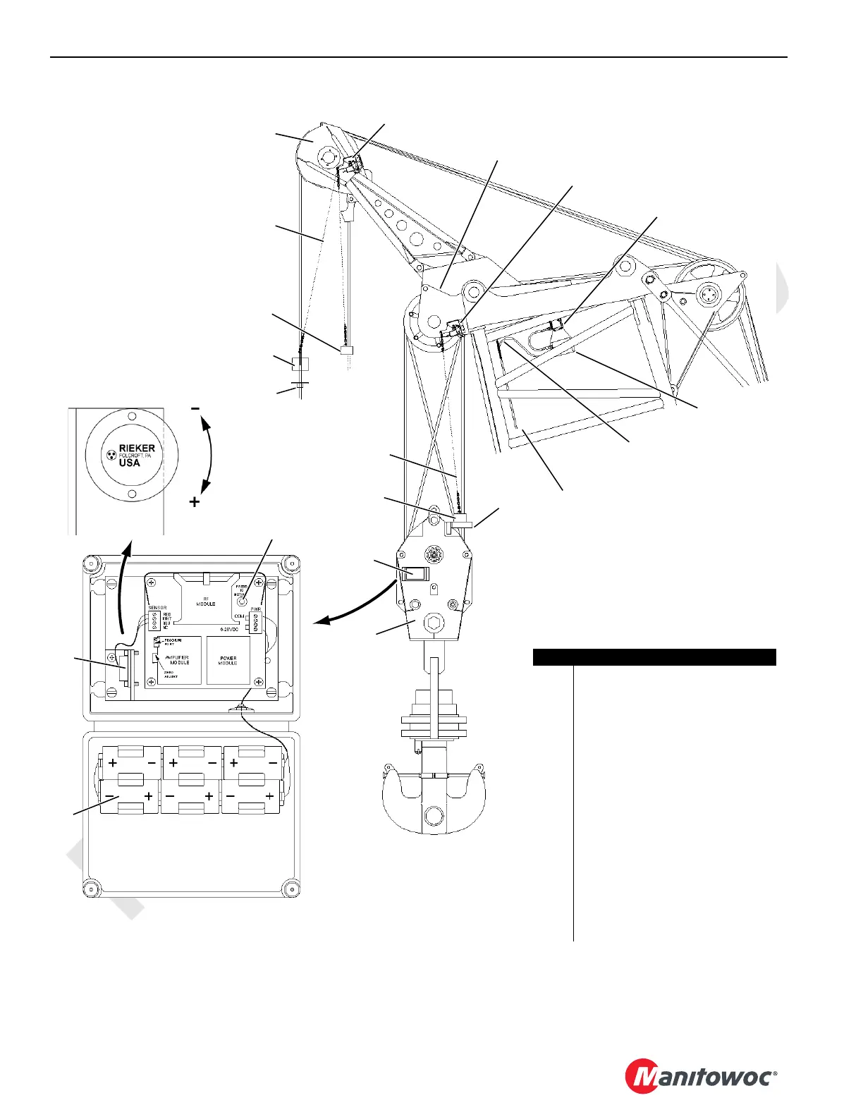
FIGURE 5-6
Strain Relief on Cable Must
be Connected to Hook
in Boom and Jib Point
Item Description
1Lift Block
2 1-Part Weight
3 Multiple Part Weight
4 Chain 8 ft (2,4 m) (1 or 2 each)
5 Upper Boom or Jib Point
6 Limit Switch Assembly
7 Lower Boom Point
8 Boom Node
9 Load Cell Receiver
10 Electric Cable From Reel
11 Lift Plate
12 Load Block
13 Chain 12 ft (3,7 m)
14 Block Angle Transmitter (optional)
15 Angle Sensor
16 Batteries
17 Press to Install Button
1
2
3
4
5
6
Weight
Multiple Part
Chain
12' (3.7 m)
11
10
9
6
8
3
13
12
Block-Up Limit at #55-79A Boom Point Shown
Block-Up Limit at #79 Boom Point, at #55 Boom
Point and at Luffing Jib Points is Similar
7
16
14
15
With European
Standard Only
17
18CSM5-106
18CSM5-107
Angle Sensor
Adjustment Direction
A15729