27
If the heater will be installed in a building that has a system that
maintains a negative pressure, it is possible for a back-draft to
allow outside air to be pulled into the heater while not in operation.
This can create a situation where freezing might occur within the
heater. Please consult a professional for a properly designed
venting solution or contact Marey.
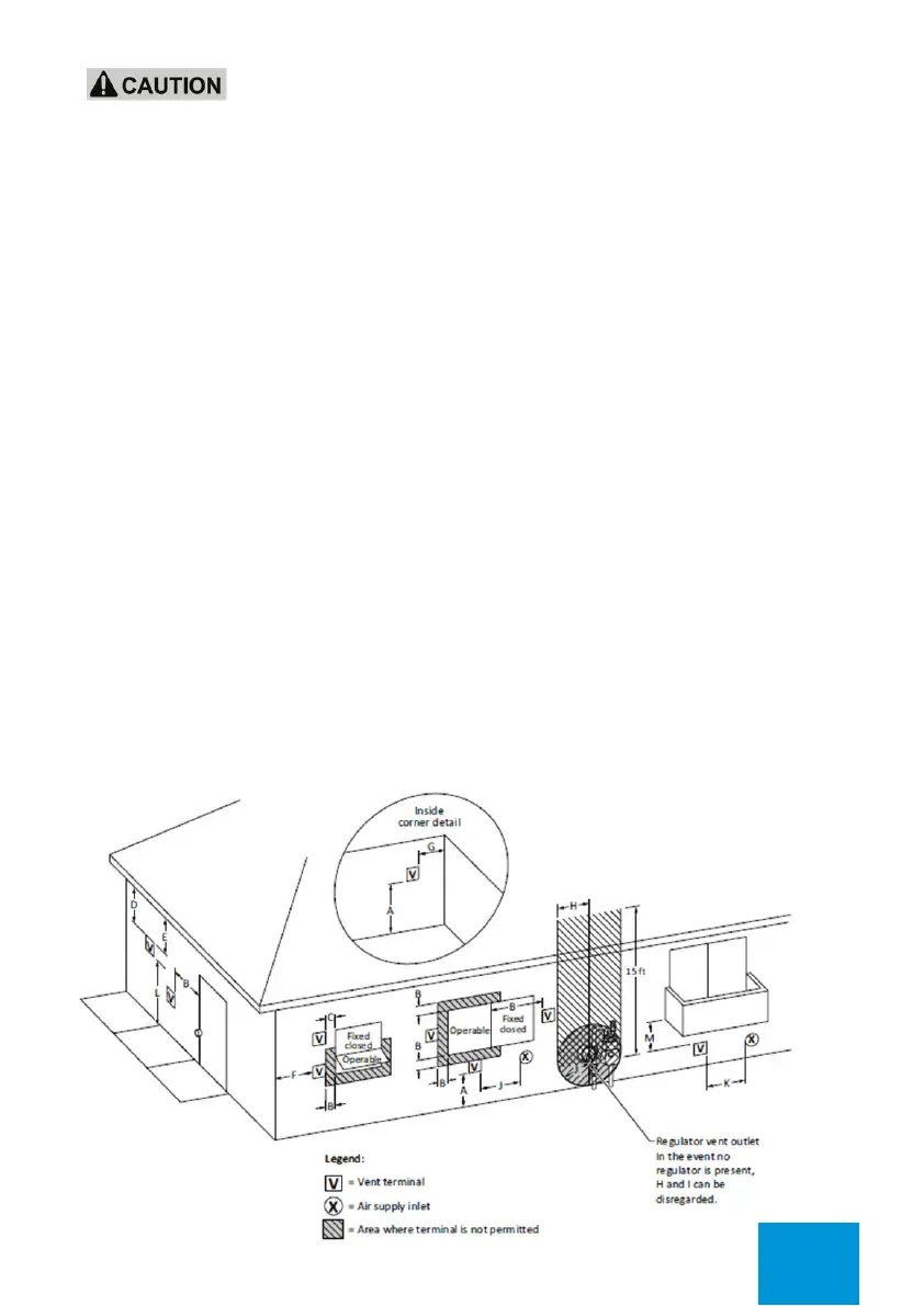
TERMINAL CLEARANCES
For water heaters other than for recreational vehicle installation, the following is information on
where the vent terminal should and should not terminate, including:
1) A diagram as shown in Figure 2-A, Direct vent terminal clearances, for direct vent appliances
or Figure 2-B, Other than direct vent terminal clearances, for other than direct vent appliances,
or equivalent, indicating vent terminal clearances A to M. The clearances marked on the diagram
shall be stated separately for US and Canadian installations and shall not be less than those
specied in the current ANSI Z223.1/NFPA 54, National Fuel Gas Code, or CSA B149.1, Natural
Gas and Propane Installation Codes, as applicable.
For clearances not specied in ANSI Z223.1/NFPA 54 or CSA B149.1, one of the following shall
be indicated:
A) a minimum clearance value determined by testing in accordance with Clause 5.17,Wall, oor,
and ceiling temperatures; or
B) a reference to the following footnote:
“Clearance in accordance with local installation codes and the requirements of the gas supplier.”
DIRECT VENTING (TWIN PIPE)
Figure 2-A
Direct vent terminal clearances
 Loading...