IS 3.5 - 4.0 - 5.0 - 6.0
- 18 -
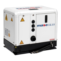
Fig. 18
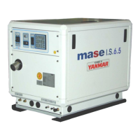
Fig. 19
CARICO
LOAD
CHARGE
CARICO
LOAD
CHARGE
RETE
MAINS
RESEAU
CARICO
LOAD
CHARGE
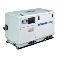
Fig. 20
Hz 50 50
V 110/220 110/220
W 2700 4000
A 12.3 18
IS 3.5 IS 5.0 - 6.0
Hz 60 60
V 120/240 120/240
W 2900 4800
A 12.1 20
IS 5.0 - 6.0
IS 3.5
Hz 50 60 50 60
V 110 120 220 240
W. 2700 2900 2700 2900
A 24.5 24.2 12.3 12.1
TAB 1
Hz 50 60 50 60
V 110 120 220 240
W. 4000 4800 4000 4800
A 36.5 40 18 20
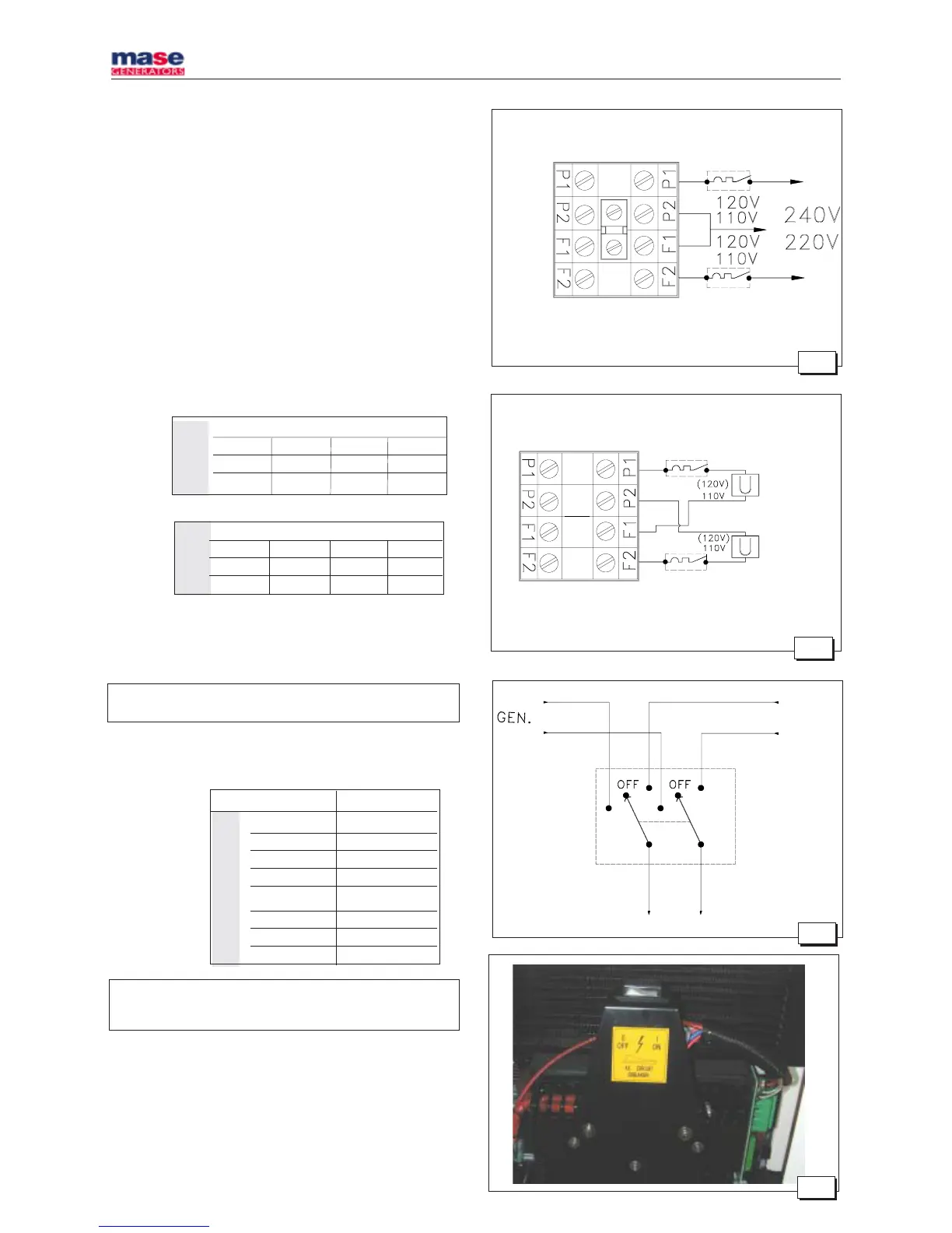
Fig. 21
- Ensure that the sum of the loads to be supplied does not
exceed the nominal power of the electric generator.
- Magnetothermic protective devices or similar should be
placed between the generator and electrical equipment,
according to the tables shown below.
- To make both parallel and serial connections, use the
special bridges provided in the accessories to the
electric generator on the terminal board fig. 15 ref. 1.
Single voltage distribution
.
N.B: In these cases just one magnetothermic device should be
installed, see fig. 16/17.
Double voltage distribution
N.B: In these cases two magnetothermic devices should be installed,
see fig. 18/19, dimensioned on the current values (A) shown in
Table. 2.
4.4. Generator - Mains switching
A switch should be placed on the line to switch the user
appliances from the generator to an external power line.
The switch should be dimensioned according to the size
of the loads: a general diagram is shown in fig. 20.
 Loading...