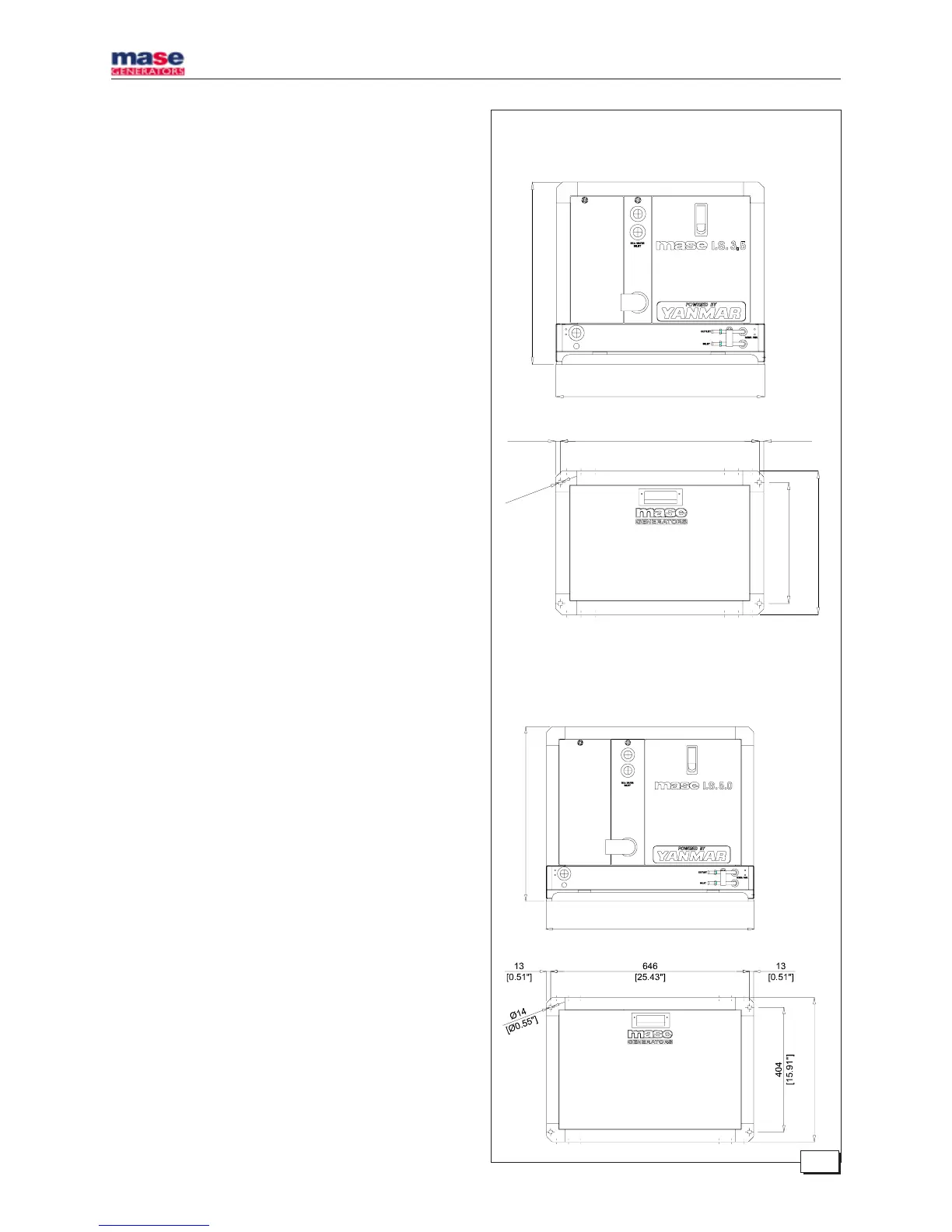
IS 3.5 - 4.0 - 5.0 - 6.0
- 4 -
565
[22.24"]
675
[26.57"]
468
[18.43"]
Fig. 1
IS 3.5 - 4.0
IS 5.0 - 6.0
515
[20.28"]
590
[23.23"]
562
[22.13"]
342
[13.46"]
13
[0.51"]
13
[0.51"]
Ø
1
4
[
Ø
0
.
5
5
"
]
406
[15.98"]
1.0. INSTALLATION
1.1. Characteristics of the installation space
The generator must be installed in a sufficiently aired
space, supplying a little amount of air necessary for the
combustion of the motor.
The space must be separate and acoustically insulated
from living areas.
The generator should be positioned so that normal
maintenance operations can easily be carried out.
Propulsion motors are recommended for installation in the
area as long as they comply with the above-mentioned
conditions.
1.2. Fastening the unit to the ground
To fasten the unit securely, a base should be installed to
absorb vibrations and support the weight.
Drill holes in the base according to the instructions in
fig. 1.
1.3. Ventilation
The generator is equipped with an internal forced cooling
system through a water/air exchanger.
The air needed for combustion is taken in through the
opening on the base (fig. 2) so care must be taken to
ensure that this opening is always free.
2.0. COOLING WATER CIRCUIT
In electric generator , the motor is cooled by an open-
circuit system in which sea water circulates.
The capacity of the sea water circuit is 1200 lt / h .
On installation a sea water feed circuit should be fitted for
cooling and a waste system to expel the mixture of flue
gas and water.
2.1. Sea water feed system
Boats usually use one of two systems to collect water
(fig. 3):
1 - Direct infeed system
2 - System with baffle
 Loading...