Page 7
1. CLOUD S
YNCRO
230VAC: runs on grid tension of 110/230V~ (a.c.), 50/60Hz
(±10%), with a five wire cable (L
IGHT
B
LUE
, common neutral; B
LACK
, phase
open; B
ROWN
, phase closed). The additional wiring (R
ED
and W
HITE
) is for
electronic synchronisation (NEKOS Patent).
2. CLOUD S
YNCRO
24VDC: runs on 24V═ (d.c.), with five wire cable, B
LACK
“1”,
connected to the + (positive) closes; B
LACK
“2”, connected to the + (positive)
opens. The third wire B
LACK
“3”
has to be insulated and never connected (it’s
used for special applications). The additional wiring (R
ED
and W
HITE
) is for
electronic synchronisation (NEKOS Patent).
Low tension actuators 24V═ (d.c.) can be powered using a feeder with an output tension
of 24V═ (d.c.) (-15% ÷ +20%, or min. 20.4V, max. 28.8V). The feeder must be approved
and class II (double safety insulation).
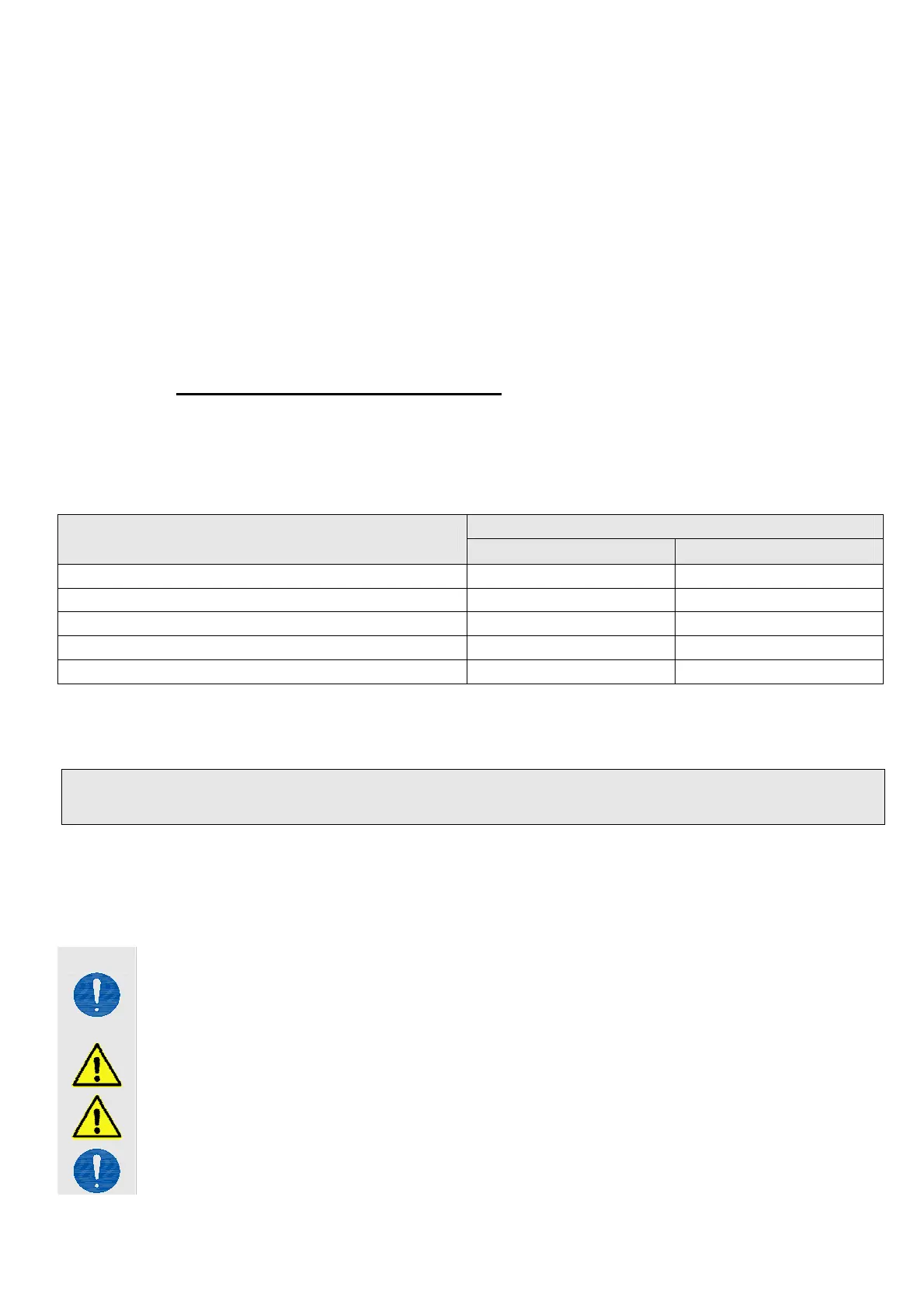
7.1. Section choice of supply cables
In low tension supply systems, tension falls due to current passage in conductors is a
basic aspect for safety and good appliance function. It is therefore extremely important
that the conductor section in function of cable length is calculated correctly. The
following table indicates cable lengths for an actuator connected at nominal charge.
Cable section
Actuator using
24 V
═
230V
~
4,00 mm
~ 1.000 m ~ 3.000 m
2,50 mm
~ 750 m ~ 2,200 m
1,50 mm
~ 450 m ~ 1,350 m
0,75 mm
~ 160 m ~ 500 m
0,50 mm
~ 130 m ~ 400 m
8. Assembly
These indications are intended for the attention of technicians and specialized
personnel. Basic job and safety techniques are therefore not included.
All preparatory operations, assembly and electrical connections must be carried out by
technical and specialized personnel to guarantee best performances and good function
of the CLOUD SYNCRO chain operated actuator. First of all, please check that the
following fundamental points have been satisfied:
Actuator specifications must be sufficient for movement of the window without
encountering any obstacle. The limits indicated in the technical data table must
not be superseded (page 6) and the most appropriate stroke should be selected.
Calculations should be checked using the formula indicated on page 4.
Attention. Check that the electrical power supply corresponds to that indicated
on the TECHNICAL DATA label on the machine.
Ensure that the actuator has not been damaged during transport, first visually
and then by powering in both directions.
Check that the width of the inside of the window (where the actuator is to be
assembled) is over 405 mm, otherwise the actuator should not be installed.
 Loading...