L (phase)
N (neutral)
gray
brown
blue
yellow/green
black
MAIN
POWER SUPPLY
motor
cable
Command buttons
(optional)
2.1 Warnings for the ELECTRICIAN
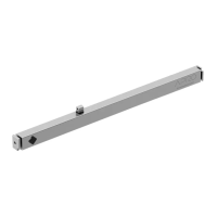
Make connections with power supply disconnected Check that the power supply does not depend from electrical circuits for lighting Always connect the motor to the grounding
system (yellow/green) The supply line must be equipped with a circuit breaker. The supply line must be fitted with a device with a voltage category III, i.e. the distance between the
contacts must be of 3,5 mm at least The product doesn’t not provide any protection against overloads or short circuits. Provide the supply line with an adequate protection to the load,
for example a fuse of maximum value 3,15A You must use buttons with spring return ("hold-to-run" type), do not use buttons with maintained position Command buttons are
connected to the main voltage, so they must be properly insulated and protected The section of the connecting cables must be proportionate to their length and to the absorption of
the load, and in any case not less than 1,5 mm
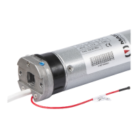
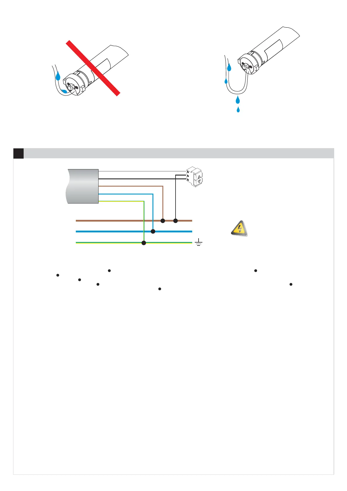
2.2 POWER SUPPLY
The electrical specifications for motor operation are shown in the label applied to the tube of the motor.
The supply voltage must be applied to the brown (PHASE) and blue (NEUTRAL) wires. Connect the green / yellow wire to the grounding system.
2.3 COMMAND BUTTONS
The command buttons are optional. The command buttons must be connected to the black and gray wires and they must close on brown wire. You must use
buttons with spring return (“hold to run” type), do not use buttons with maintained position. More command buttons can be connected via a parallel
connection. The control buttons are subject to the mains voltage and therefore should be properly insulated and protected. In the case where the command
buttons are not used, it is necessary to ensure the isolation of black and gray wires.
2.4 INTERFACING WITH HOME AUTOMATION CONTROL UNIT
The control outputs of the Home Automation Control Unit (following H.A.C.U.) must be connected to the command inputs of the motor (GRAY and BLACK
wires), replacing the manual buttons. Consequently, the H.A.C.U. must comply with the rules of operation of the command buttons, depending on whether the
command buttons work in PULSE mode (factory setting) or in HOLD TO RUN mode (see section 10 " Logic of command buttons").
Rules that the H.A.C.U. must comply to control the device operating with buttons in PULSE mode.
a) The H.A.C.U. must not measure the current drawn by the command inputs of the device (which absorb less than 1 mA).
b) The H.A.C.U. must be connected to the device as shown, substituting the command buttons with the outputs of the H.A.C.U..
c) To operate the motor, the H.A.C.U. must close contact (up or down) for more than 0.5 seconds (typically using a pulse duration of 1 second).
d) To stop the motor, the H.A.C.U. must close contact (up or down) for 0.5 seconds or less (typically using a pulse duration of 0.2 seconds).
b) The H.A.C.U. must be connected to the device as shown, substituting the command buttons with the outputs of the H.A.C.U..
c) To allow the conclusion of the entire opening / closing, the H.A.C.U. must be able to close the contact UP / DOWN to the time required for the motor to
perform the complete operation.
Rules that the H.A.C.U. must comply to control the device operating with buttons in HOLD TO RUN mode.
At the time of this document printing, specific issues related to the connection between MASTER products and H.A.C.U. are not known (if you follow the rules
above). However MASTER disclaims any responsibility concerning the non-compatibility (even partial) with any H.A.C.U.. If the H.A.C.U. uses KNX protocols
or similar, contact the vendors of home automation controller informing them of the rules above. Probably the manufacturer of H.A.C.U. can provide
appropriate interfaces to connect the device to the H.A.C.U..
d) To stop the motor, the H.A.C.U. must be able to re-open the contacts UP / DOWN at any time.
a) The H.A.C.U. must not measure the current drawn by the command inputs of the device (which absorb less than 1 mA).
ELECTRICAL CONNECTION
02
2
 Loading...