The C38 can be placed upright on a table or shelf, standing on its own plastic feet. It can
also be installed in an optional Mcintosh L72 equipment cabinet. Follow the mounting instruc-
tions enclosed with the L72 cabinet.
The C38 can also be custom installed in a piece of furniture or cabinet of your choice.
The required panel cutout and unit dimensions are shown on Page 18 of this manual.
Always provide adequate ventilation for your C38, even though it develops very little heat.
Cool operation insures the longest possible operating life for any electronic instrument. Do
not install your C38 directly above a heat generating component such as a high powered
amplifier. In a system stack, the power amplifier should always be at the top. If all the com-
ponents are installed in a single cabinet, a quiet running ventilation fan can be a definite asset
in maintaining all the system components at the coolest possible temperatures.
A custom cabinet installation should allow the following recommended minimum spacing
dimensions for cool operation. Allow at least 1 1/2 inches (3.8cm) above the unit so airflow
is not obstructed. Allow 17 inches (43.2cm) depth behind the mounting panel, which includes
clearance for connectors. Allow 1 1/8 inches (2.9cm) in front of the mounting panel for knob
clearance.
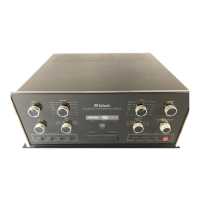
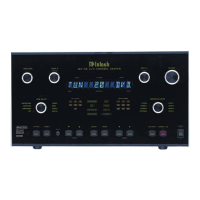
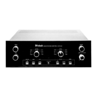
The back cover of this manual folds out to show photographs of the front and rear
panels of the C38. Fold it out to assist you in identifying and locating the front panel
controls, switches, pushbuttons, and the rear panel connectors. The letters and
numbers on the photographs refer to the information that follows.
A. BASS AND TREBLE
Provide 12dB boost and cut, with neutral flat response at the center detent position. The
Bass and Treble controls affect only the MAIN, SWITCHED 1 and 2 and BALANCED (Area
A) outputs.
B. RECORD
Selects the program signal that will feed the TAPE 1, TAPE 2, TAPE 3 and Area B OUT-
PUT jacks.
C. INFRARED SENSOR
This IR sensor accepts commands from the HR38 hand held remote controller.
D. LISTEN
Selects the program signal that feeds the MAIN, SWITCHED 1 and 2, and BALANCED
(Area A) outputs.
E. VOLUME
Adjusts the volume level at the MAIN, SWITCHED 1 and 2, AND BALANCED (Area A)
outputs. The volume level can be controlled by manually adjusting the VOLUME knob, or press-
ing the appropriate (Up) or (Down) button on the HR38 hand held Remote Controller.
The volume level is controlled in remote Area B by using the HR38 transmitting to a
wall mounted IR sensor or by a WK-1 keypad.
The TAPE OUTPUT and Area B volume levels are not affected by the C38 front panel
VOLUME control settings.
TURN ON CHARACTERISTICS
Area A: The Program signal and volume settings last used will be in effect.
Area B: The Tuner signals will automatically be selected with volume at 50dB below maximum.
6
FRONT PANEL
CONTROLS,
SWITCHES
AND
PUSHSBUTTONS
HOW TO
INSTALL
THE C38
 Loading...