IOMM AGR AGR 055A through 100A 43
Software Description (Global UNT Interface Kit required to read or
change variables)
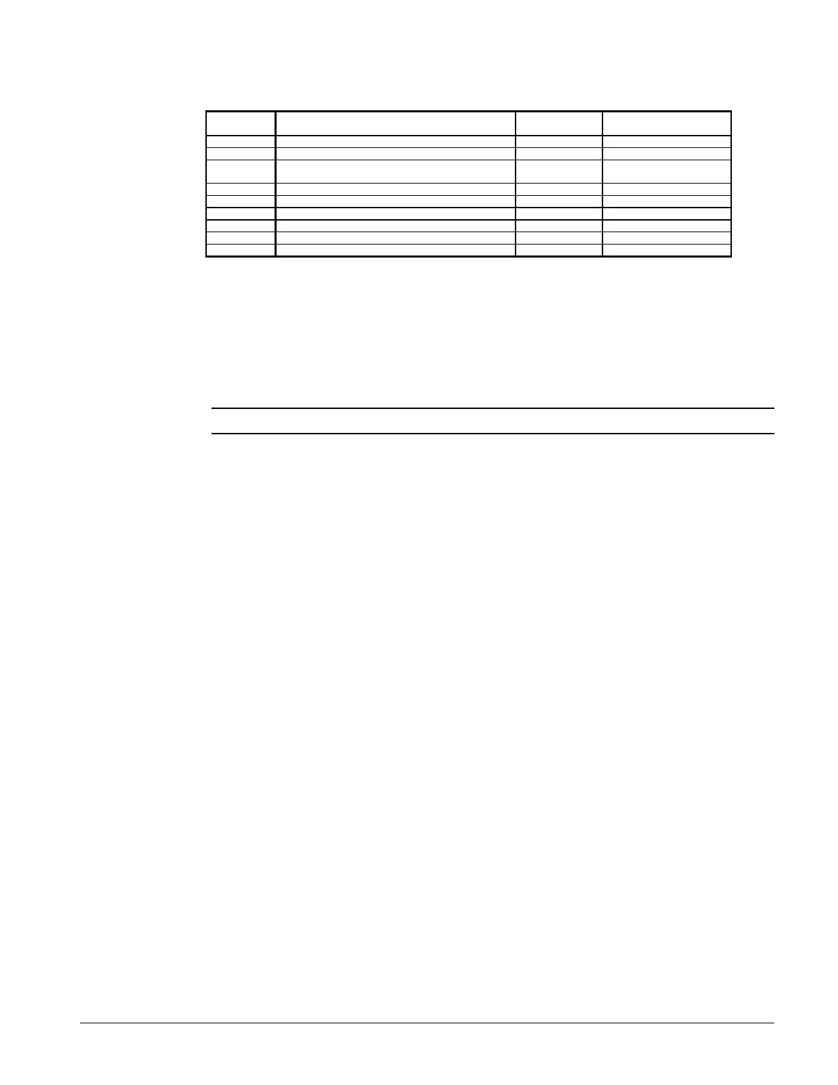
Variable
Name
Description Default Value Range
LPSS Low Pressure Starting Setpoint 10 psi 5 to 15 psi
SLPT Starting Low Pressure Time 260 sec 90 to 300 seconds
MLPS Minimum Low Pressure Setpoint 5 psi Calculated (LPSS-LPSD)
5 psi
LPSD Low Pressure Starting Differential 5 psi 3 to 10 psi
LPFS Low Pressure Freezestat setpoint 54 psi 30 to 55 psi
LPHL Low Pressure High Limit 57 psi 40 to 60 psi
LPLL Low Pressure Low Limit 55 psi 40 to 55 psi
FSTP Freezestat Time Period 60 sec 60 seconds fixed
PDTD Pumpdown Delay Time Period 60 sec 60 seconds fixed
Hot Gas Bypass (Optional)
This option allows the system to operate at low loads without the ON-OFF cycling of the
compressor. When the hot gas bypass option is used it is required to be on both refrigerant circuits
because of the lead / lag feature of the Global UNT controller.
This option allows passage of discharge gas into the evaporator inlet (between the TX valve and the
evaporator) which generates a false load to supplement the actual chilled water load.
Note: The hot gas bypass valve cannot generate a 100% false load.
The valve that is supplied can provide a load of approximately 10 tons. The system load added to
the ten tons of the hot gas bypass valve has to exceed the compressor capacity for stage 1 compressor
operating unloaded for stable system operation. This requires some system load. When using hot
gas bypass, the optional six stage capacity staging unit is recommended.
A solenoid valve in the hot gas bypass lines is wired in parallel with both circuit’s liquid line
solenoid valves SV1 and SV2. The hot gas bypass is available whenever a refrigerant circuit is
operating. The hot gas valve is regulating by the evaporator pressure and the remote adjustable
bulb. The pressure regulating valve is factory set to begin opening at 58 psig (32°F for R-22). This
setting can be changed by adjusting the remote adjustable bulb. Remove the cap on the remote bulb
and raise the pressure by turning the adjustment screw clockwise. Lower the pressure by turning the
adjusting screw counterclockwise. This changes the pressure that the hot gas bypass valve will start
to open. Do not force the adjusting screw as this can damage the adjusting assembly.
NOTE: The hot gas line may become hot enough to cause injury. Be careful during valve
checkout.
NOTE: The remote adjusting bulb must be installed on the outside of the suction line
insulation. The bulb has to have a stable ambient air temperature for proper operation.
Placing the bulb in contact with the evaporator refrigerant line will limit the operation of the
hot gas bypass valve.
Filter Driers
Each refrigerant circuit is furnished with a full flow filter drier or an optional replaceable core type
filter-drier. The core assembly of the replaceable core drier consists of a filter core held tightly in
the shell in a manner that allows full flow without bypass.
Pressure drop across the filter drier at full load conditions must not exceed 10 psig. If pressure
drop is more than 10 psig, then replace the filter drier.
NOTE: Pump out refrigerant before removing end flange for replacement of core(s).
A condenser liquid line service valve is provided for isolating the charge in the condenser, but also
serves as the point from which the liquid line can be pumped out. With the line free of liquid, the
filter-drier core(s) can be easily replaced.
 Loading...