12 AGR 055A through 100A IOMM AGR
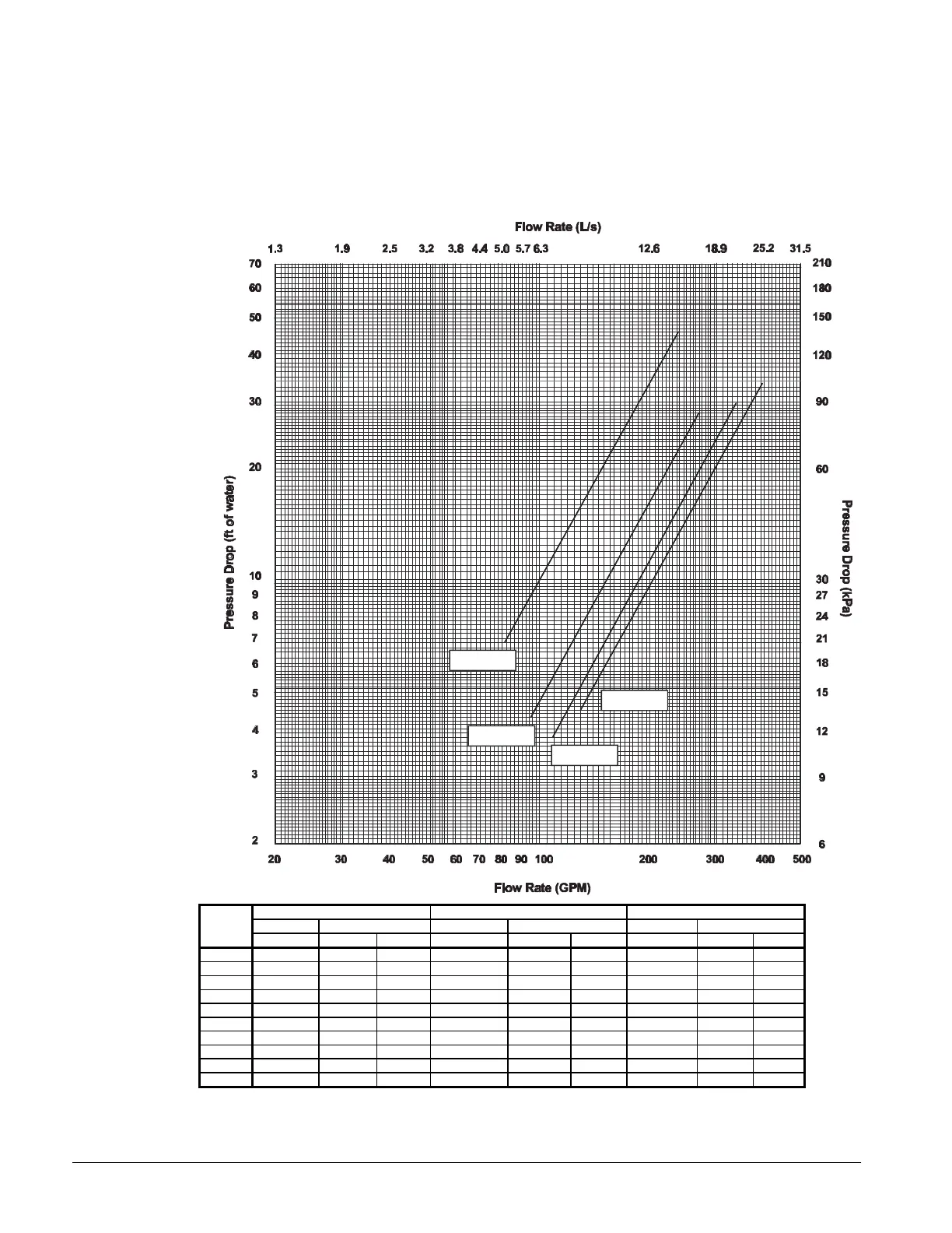
Evaporator Water Flow and Pressure Drop
Evaporator flow rate must fall between the minimum and maximum values shown in the evaporator
pressure drop table on page 12. Varying chilled water flow through the evaporator while the
compressor(s) are operating is not recommended.
Figure 8, Pressure Drop Curve
055-060
065-070
075-085
NOMINAL MAXIMUM MINIMUM
Unit PD Flow PD Flow PD Flow
Size (ft) of Water (gpm) (lps) (ft) of Water (gpm) (lps) (ft) of Water (gpm) (lps)
055AS 15.8 130 8.20 39.7 217 13.67 6.8 81 5.13
060AS 18.5 142 8.96 46.6 237 14.93 8.0 89 5.60
065AS 10.0 152 9.59 25.1 253 15.98 4.3 95 5.99
070AS 11.2 162 10.22 28.1 270 17.03 4.8 101 6.39
075AS 8.9 172 10.85 22.5 287 18.09 3.8 108 6.78
080AS 10.3 187 11.80 25.9 312 19.66 4.4 117 7.37
085AS 11.8 202 12.74 29.7 337 21.24 5.0 126 7.97
090AS 10.5 208 13.12 26.3 347 21.87 4.5 130 8.20
095AS 12.0 224 14.13 30.0 373 23.55 5.2 140 8.83
100AS 13.4 238 15.02 33.6 397 25.02 5.7 149 9.38
Minimum and maximum flows are established to ensure the Delta-T for each unit size falls within the 6 - 16°F range for proper
unit control. Contact factory for unit operation outside of minimum and maximum flows shown.
 Loading...