12 McQuay IM 660-3
Service Information
Inputs and Outputs
Analog Inputs
The MicroTech WSHP unit controller has six standard analog
inputs. See Table 7. The controller can sense temperatures in
the range of 0° to 158°F (–18° to 70°C).
Digital Inputs
The water source heat pump controller has four standard digital
inputs. See Table 8. Digital input conditioning includes RC
filtering with a time constant of at least 4.7 milliseconds. The
base module provides additional filtering using software filtering
techniques.
The digital inputs sense the presence or absence of an external
24 VAC ± 20% power source with a minimum of 10 mA AC
current flowing through the following isolated contacts:
Refer to the wiring diagram supplied with your unit for
specific wiring details.
Digital Outputs
All digital outputs, with the exception of the on-board and off-
board status LEDs, are capable of controlling electromechanical or
solid state relays. They switch inductive loads at 24 VAC ± 20%,
0.4 pF and at the steady state AC RMS currents listed in Table 9
(10x single cycle surge currents are assumed on initial turn on).
The on-board and off-board status LEDs are controlled by one of
the Neuron’s I/0 pins capable of PuIse Width Modulation.
Input/Output Tables
All WSHP controller input and output connections and their
corresponding water source heat pump components are shown
in Table 10 on page 14.
Test Procedures
Microprocessor Problems
The status LED indications can aid in WSHP controller
diagnostics. Approximately 40 seconds after power is applied to
the WSHP, the status LED should illuminate as shown in
Table 2 on page 2. If not, either there is a software problem or
the WSHP controller is defective.
Power Supply Problems
The WSHP controller requires a 24 VAC power supply. It is
connected to the board at the section labeled 24V GND and
24 VAC (terminals J41 and J42). Refer to the unit wiring
diagram. If you suspect a problem with the WSHP controller
power, check the following:
1 Verify that the main power switch is at ON.
2 Check the voltage at the secondary of the transformer. It
should be approximately 24 VAC (load dependent).
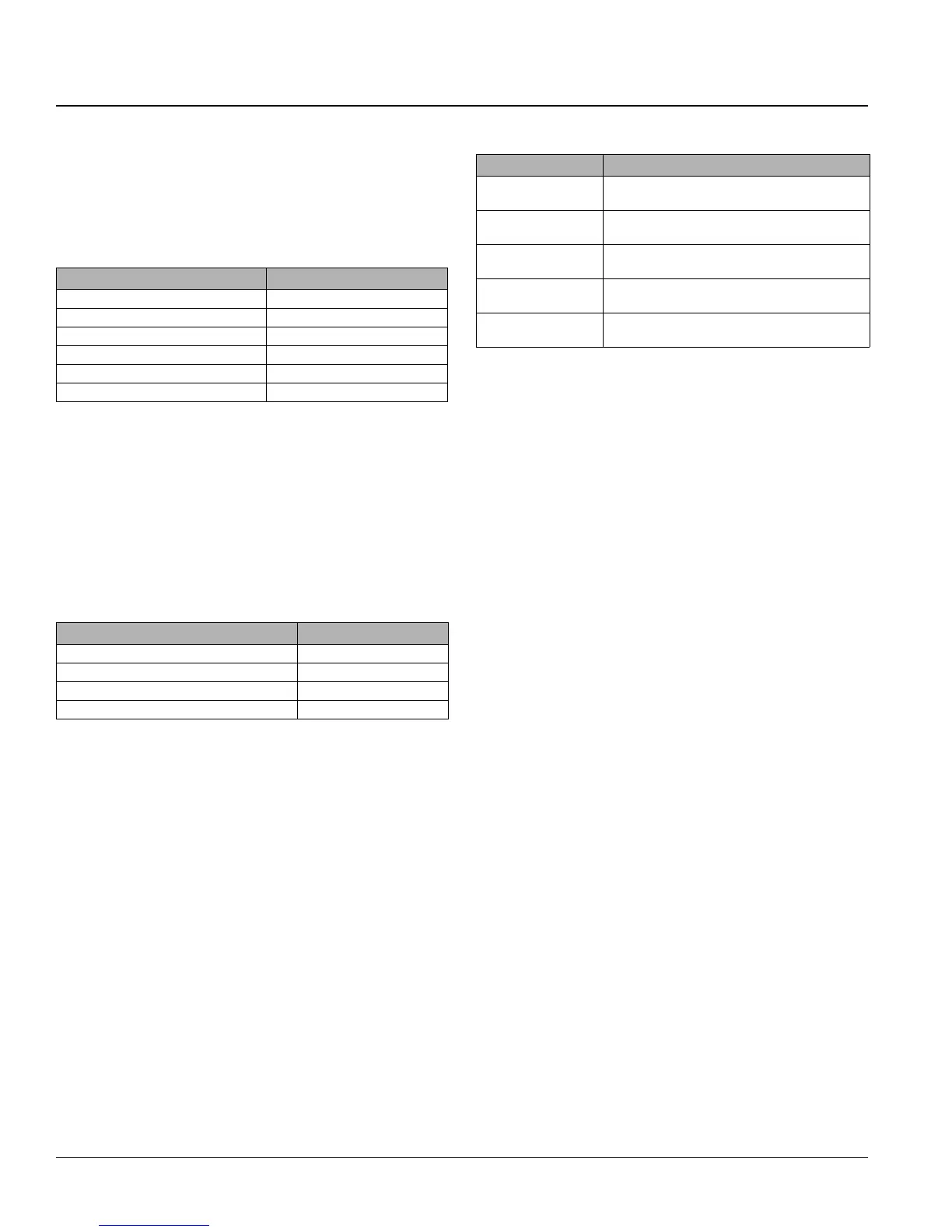
Table 7: Analog inputs
Description Location
Discharge air temp sensor Inlet to fan
Leaving water temp sensor Leaving water line
Condensate overflow sensor Condensate drain pan
Brownout (supply voltage) sensor On board
Room air temp sensor Remote basic wall sensor
Tenant override/set point adjust Remote wall sensor
Table 8: Digital inputs
Description Location
Refrigerant high pressure—N/C HP switch
Refrigerant low pressure—N/C LP switch
Refrigerant low temp—N/C LT switch
Remote start/stop—N/O Remote switch
Table 9: Digital outputs
Description Type/AC RMS current rating
Fan contactor
E/M pilot duty relay at 300 mA-AC
(SPST N/O contacts)
Compressor contactor
E/M pilot duty relay at 300 mA-AC
(SPST N/O contacts)
Reversing valve
solenoid
E/M pilot duty relay or SS random turn on Triac
at 600 mA-AC (SPST N/O contacts)
On-board status LED
Off-board status LED
Yellow
DC-sourced signal—current limited to 10 mA-DC
Multi-purpose (spare)
isolated E/M contacts
E/M pilot duty relay at 300 mA-AC
(SPST N/O contacts)

 Loading...


