McQuay IM 777-4 25
Service and Maintenance
MVP Variable Speed Sheaves
Mounting
1 Verify both driving and driven sheaves are in alignment
and the shafts are parallel. The centerline of the driving
sheave must be in line with the centerline of the driven
sheave. See Figure 37, page 26.
2 Verify that all setscrews are torqued to the values shown
in Figure 17, page 25 before starting drive. Check
setscrew torque and belt tension after 24 hours of
service.
Adjusting
1 Adjust motor base forward to release belt tension.
Remove the belts for easier adjustment.
2 Loosen, but do not remove both of the locking setscrews
A in the outer locking ring by using a hex key or torque
wrench with a hex bit.
3 Adjust sheave to desired pitch diameter by turning the
outer locking ring. Use a spanner wrench or drift inserted
into the three holes that are located 120° apart on the
ring.
4 Any pitch diameter can be obtained within the sheave
range. One complete turn of the outer locking ring
changes the pitch diameter 0.233".
5 Do not open sheaves more than the following:
a Do not open B sheaves more than 4 3/4 turns for the A
belts or 6 turns for the B belts.
b Do not open C sheaves more than 9 1/2 turns.
c Do not open 5V sheaves more than 6 turns.
d Do not open 8V sheaves more than 8 turns.
6 Tighten BOTH locking screws A in the outer locking
ring before operating the drive. Use a torque wrench and
tighten to the value shown in Table 17.
7 Replace belts and adjust the motor base to tension the
belts properly. See Fan Drive Belt‚ page 26.
8 Do not loosen any screws other than the two locking
screws
A in the outer locking ring when adjusting the
sheave pitch. Do not operate the drive until the locking
screws have been set to the torque specifications.
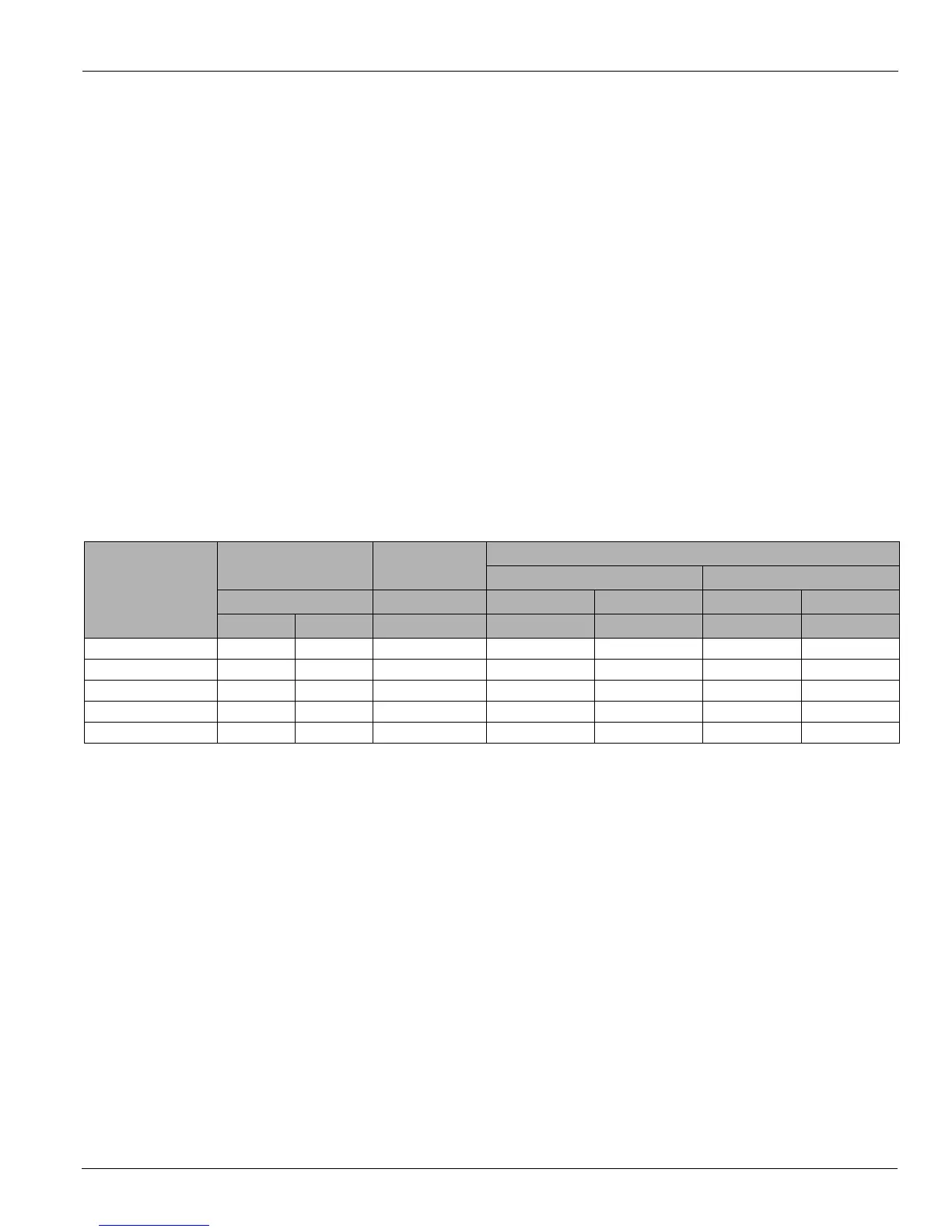
Table 17: Screw Torque Values
Nominal screw size
(dia–-thds/in)
Socket head cap screws
Flat head socket
screws
Hollow head set screws only
Lengths equal or greater than dia. For lengths (L)) less than dia.
Seating torque Seating torque Seating torque Seating torque Length (L) Seating torque
(in–lbs) (in–lbs) (in–lbs) (in–lbs) (in–lbs) (in–lbs) (in–lbs)
1/4–20NC 150 12.5 100 87 7.3 3/16 50
5/16–11NC 305 25.4 200 165 13.8 1/4 90
3/8–16NC 545 45.4 350 290 24.2 1/4, 5/16 150, 250
1/2–13NC 1300 108.3 N/A 620 51.7 N/A N/A
5/8–11NC N/A N/A N/A 1225 102.1 N/A N/A

 Loading...