6 McQuay IM 777-4
Mechanical Installation
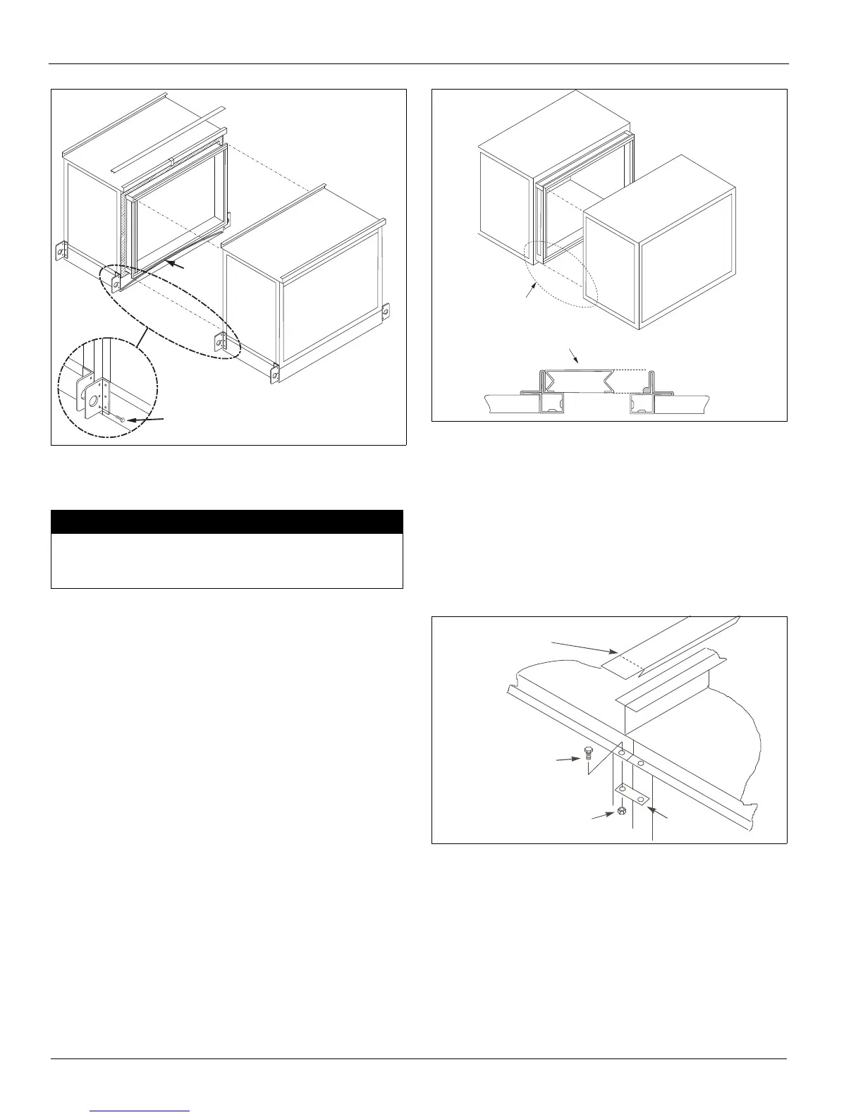
Figure 7: Fasten Bottom of Section
d A length of “D” gasket is attached to each section
(Figure 7). This gasket MUST be installed to the unit
base section.
e Handle units with curb-ready bases and vestibules so
the lifting bracket can be removed after the unit is
placed on the curbing.
Note: Remove the lifting bracket that projects inward over
the curbing. Save the self tapping screws. When the
adjacent section is placed in position, use self
tapping screw to secure the bases together.
Figure 8: Internal Fastening
1 Check that the sealant is compressed between the mating
channels when the unit sections are joined. Touch up any
places where gaps are noted.
2 After sections are seated tightly together, slip the splice
cap over the top panel flanges. Bend the ends of the
splice cap down to secure in place (Figure 9).
3 Assemble the small splice plate at the top rail to secure
the sections together at the top. Use 5/16" bolts
(Figure 9).
Figure 9: Splice Cap and Splice Plate
IMPORTANT
The gasket is to be installed in an arc shape with the ends
lower than the center, so that any moisture that may reach the
gasket will be drained to the outside of the unit.
3/8" x 1" Bolt and Nut
“D”
Gasket
A
S p l i c e C o l l a r
m u s t b e a l i g n e d
t o s e a l t o g a s k e t .
5 / 1 6 - 1 8 N u t
S p l i c e
P l a t e
5 / 1 6 - 1 8 B o l t
S l i d e S p l i c e C a p o n
a n d b e n d e n d s d o w n

 Loading...